
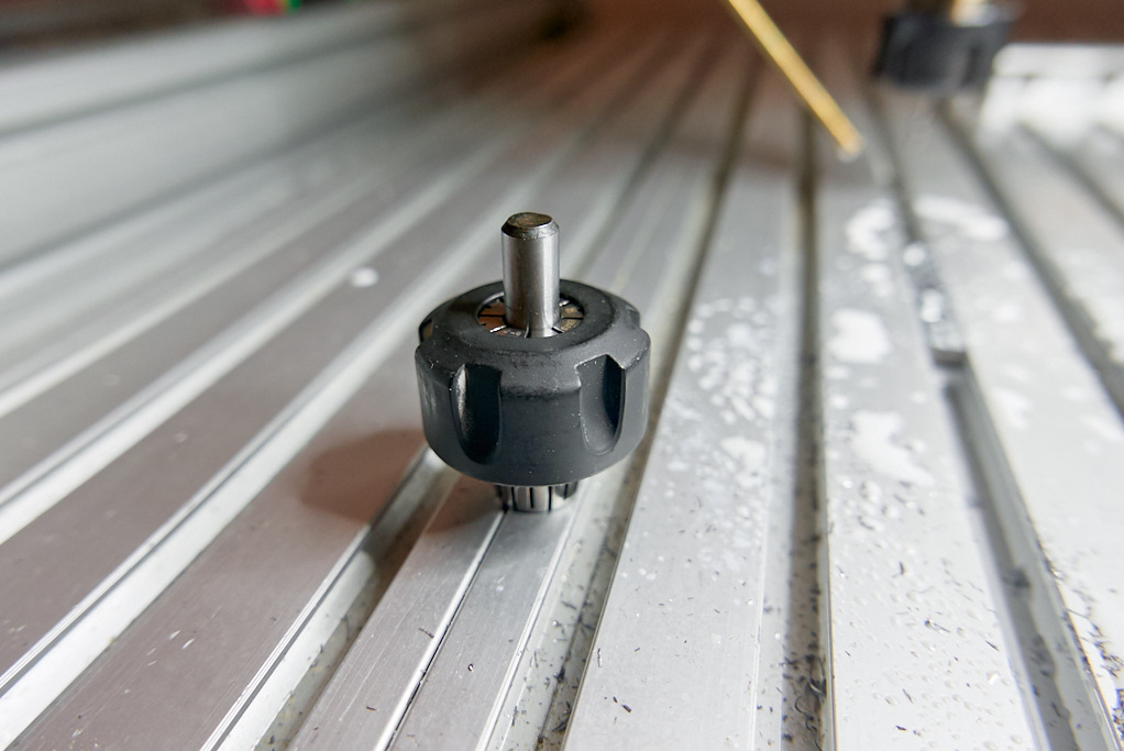
It did cross my mind at some point as the new AMB (former Kress) ATC spindle costs about the same as the Teknomotor and Delta combo. But for me an ATC would be just a nice gadget, I wouldn’t see any productivity gains. So, pure power and ER20 won in the end. To speed up tool changes I got a second collet nut 
Circuit braker, main switch, break resistor, VFD mounted on the DIN rail. The DIN back for the VFD was an extra part, forgot to show it in the original picture. Also, I ended up using a 2 pole main switch, not a 3 pole. Duh (seriously, dude? were you going to switch off the ground?) . I did not get an EMI filter as the Delta has a built-in one.

The most intimidating thing about setting up a VFD is the endless list of parameters that can be tuned. I had read the manual several times before receiving the unit. Eventually it’s only a handful of parameters that need to be set, the most important of which are the ones defining the V/f curve. Except for the pdf with the detailed description of each parameter, there’s a handy parameter summary book. Great for notes.

The V/f curve is defined by 6 values:
Fmax, Vmax
Fbase, Vbase
Fmin, Vmin
The first two couples are explicitly noted on the motor. The (Fmin,Vmin) to (Fbase,Vbase) is linear: y=a*x+b. Since the graph crosses at (0,0) it’s y=a*x. And since we know the base values 220=a*200 , then a=1.1 . Therefore y=1.1*x (or V=1.1*f). Then by selecting a min frequency, we find the min voltage. I started at 10Hz and 11V, but eventually settled for 40Hz and 44V, which basically acts as a minimum filter instructing the VFD not to spin bellow 2400RPM. Btw, there’s also a (Fmid, Vmid) couple that needs to be set. We don’t want to break the line, so this is also set at the same values as (Fmin,Vmin).

Apart from the curve, I tuned the acceleration/deceleration from the factory value of 10sec down to 3sec since I’ll be using a brake resistor. And then set the frequency source to the 0-10V input (AVI and ACM terminals) and the command source to “external” (M1 and DCM terminals). That was all.
I turned off the VFD and waited for more than 15mins before connecting the motor. I do not want to find out what kind of capacitors live inside this box  . I have kids.
The motor from the factory comes in star configuration (for 380V).

The VFD outputs 3x220V, so switching the cabling to triangle configuration (for 220V) .

Grounded and covered.

Test.

Oh no, it’s 0.0083% off. 
5 Likes
so uh, whatcha doin with that precision Makita collet?
I’ll keep it for the occasional manual/table routing. Besides, shipping it to your side of the Atlantic would cost almost as much as getting a new one from Elaire.
VFD mounted. There was an extra grounding point on the unit, which I connected to the DIN rail itself.

One of the holes on the back of the unit (almost) coincided with a hole on the shelf. I expanded the latter and bolted the unit through this hole to prevent any possibility of sagging in the long run.

While designing the moving Z plate I made an extra pair of holes maintaining the spacing of the spindle mount. That was part of the upgrade path and now it’s time to use all 3 pairs.

The mounting holes on the spindle plate are oversized by 0.5mm which allows for something less than 1deg of tramming. Having everything else square so far, this is plenty.

Spindle mounted.

The payload is now heavier, so the servos need to be re-tuned. That’s about 15mins each.

This is pretty much it.
5 Likes
Congratulations! So, how did you do on that 1.5k budget now that it’s done?
Season 1 & 2: 1.7k (main build & Z axis)
That was the original project scope. But then it started paying for itself, so I invested back into it.
Season 3: 1.2k (servos)
Season 4: 1k (vfd & spindle)
2 Likes
so in total about $4k?
Isn’t that awesome when it happens ![]()
The progress and evolution of your machine has been a good read.
2 Likes
And hopefully life insurance. ![]()
yeah!
any chance see some finished products and more shots of the build?
can’t get enough haha
@HaldorLonningdal no hiccups, no downtime, going strong
@PaulAlfaro let me share another sneak peek, a productivity tip that significantly drops setup time for repetitive tasks.
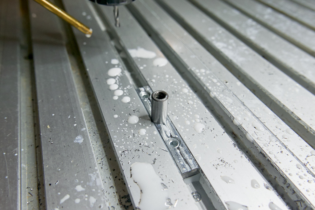
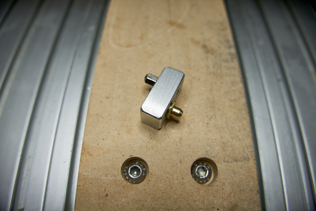
I had some long T-nuts left from the mini table saw build.
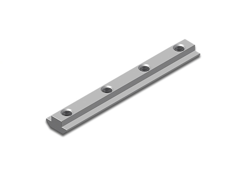
I cut one in half and milled a 8mm bore in the middle of each part.
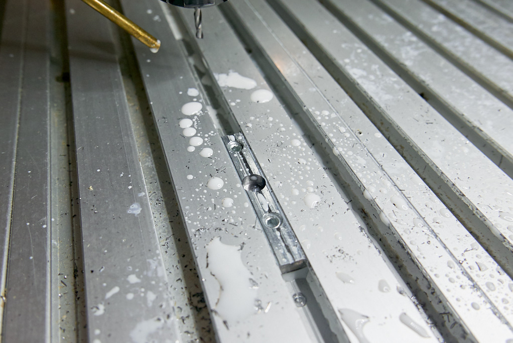
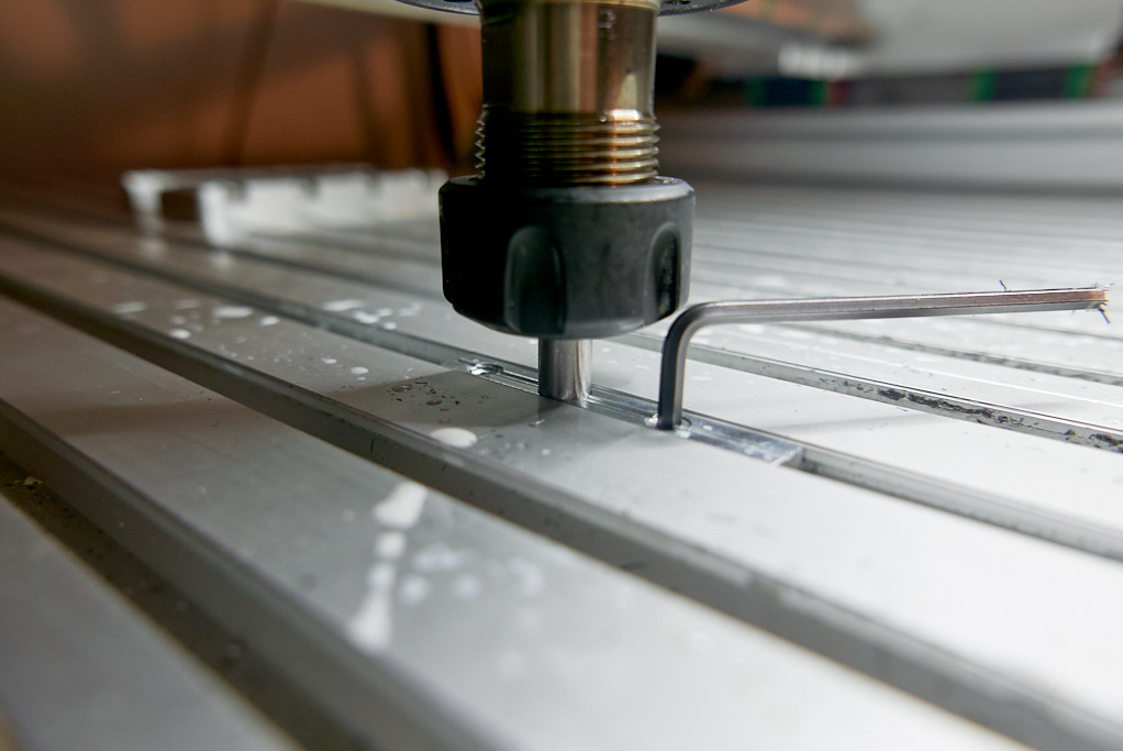
They will be used to take dowel pins for positioning fixtures. To accurately fix the t-nuts in position I inserted a dowel pin in a 8mm collet.
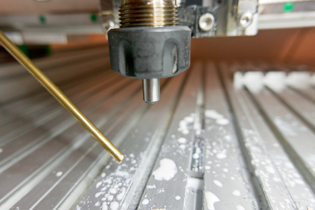
With the dowel pin as a tool, I slowly lowered it to the center of a slot.
The t-nut was loose so it could be nudged to mate with the dowel pin. Then it is fixed in place. This position is then assigned its own persistent workspace (G59) X0Y0.
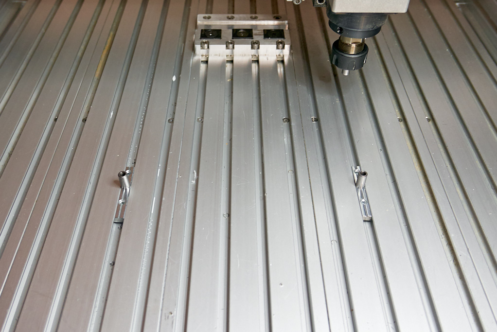
The other one was placed 210mm to the right (slots are spaced at 30mm intervals). Same process for positioning: loose t-nut, jog with dowel as tool, lower, fix. Btw, using short dowels, I’m not limited by this 210mm span.
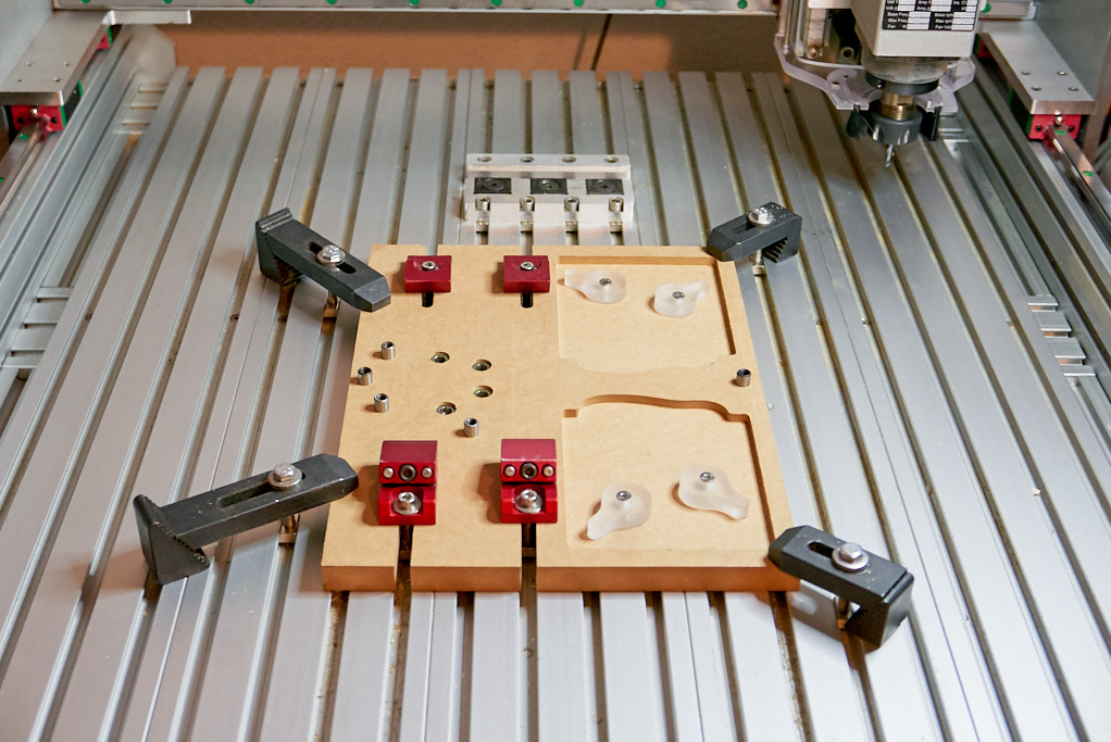
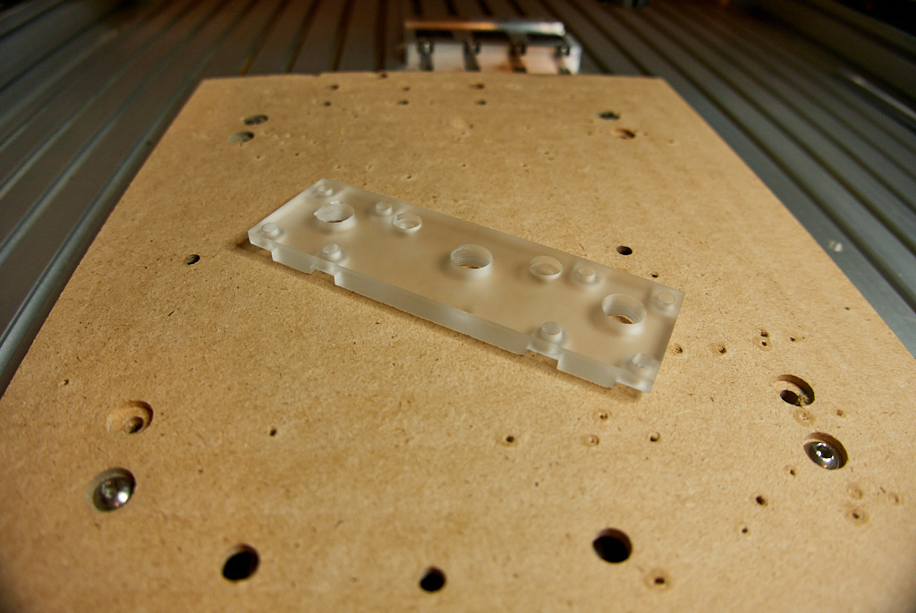
Here’s a 3-operation fixture using this setup. Once G59 is selected for postprocessing, stock is loaded, I just probe for Z and it’s ready to go.
8 Likes
That is a great idea
The machine has been sounding a bit dry lately. Time to grease it.
My only previous experience on the matter has been in the biking domain and I don’t own a grease gun. While researching about them I realized there would be some challenges.
(a.) Even though I tried to take into account the position of the grease zerks while building the machine, clearances for a typical grease gun coupler would be tight.
(b.) A grease gun seems ideal for high frequency / high volume applications, but too wasteful for low volume / low frequency. A bearing block of this size take less than one cc of grease!
(c.) The zerks on B-Carve do not look like the typical DIN 71412 stye

but rather like this
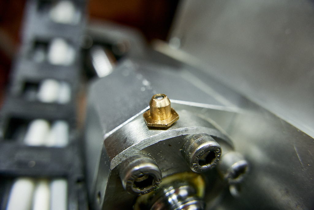
and this
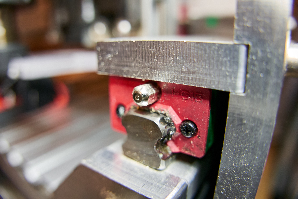
which means non-standard couplers and/or hacks in order to fit a grease gun. The 3 ballnut zerks could be replaced with standard ones (the smallest DIN 71412 zerks have the same M6 threads) but the 12 rail blocks zerks have M4 threading (no standard zerks in this size). I even made a tiny block with one of each zerk type to carry with me and go ask around and possibly test fit grease guns and couplers.
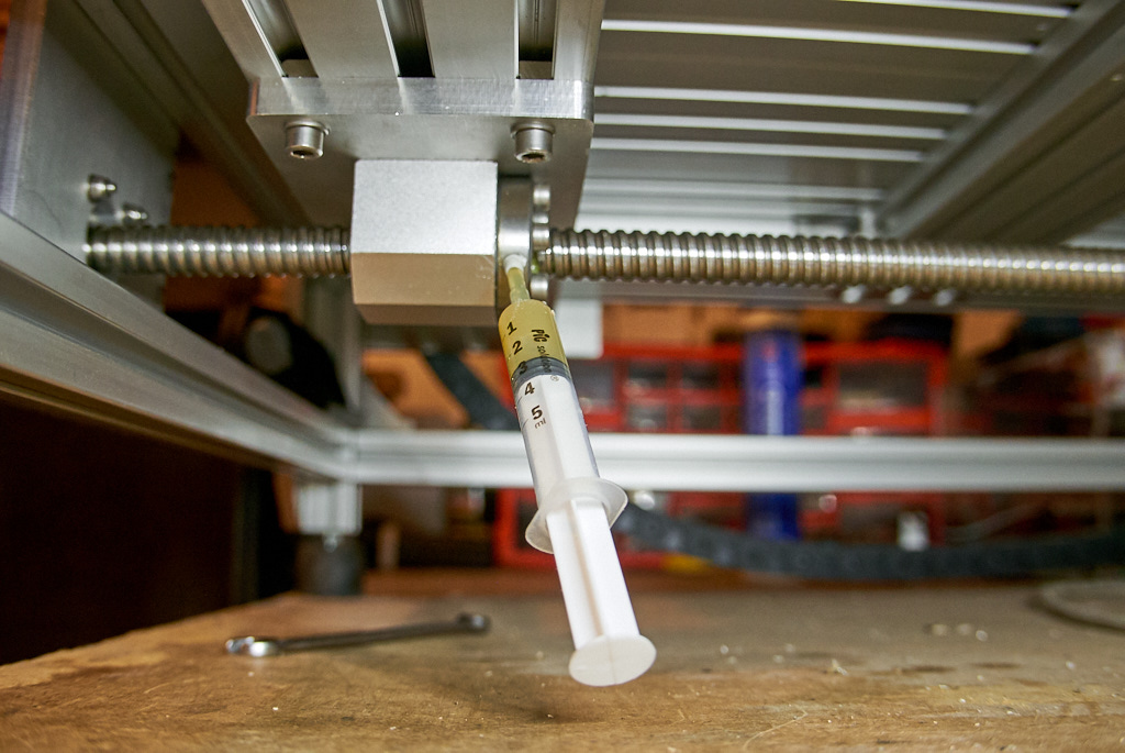
But then I had an aha moment. After re(reading) Hiwin’s lubrication manual I realized that the recommended grease types are low to mid viscosity (NLGI 1 - NLGI 2). I immediately googled for “syringe grease” and confirmed that I’m not reinventing the wheel.
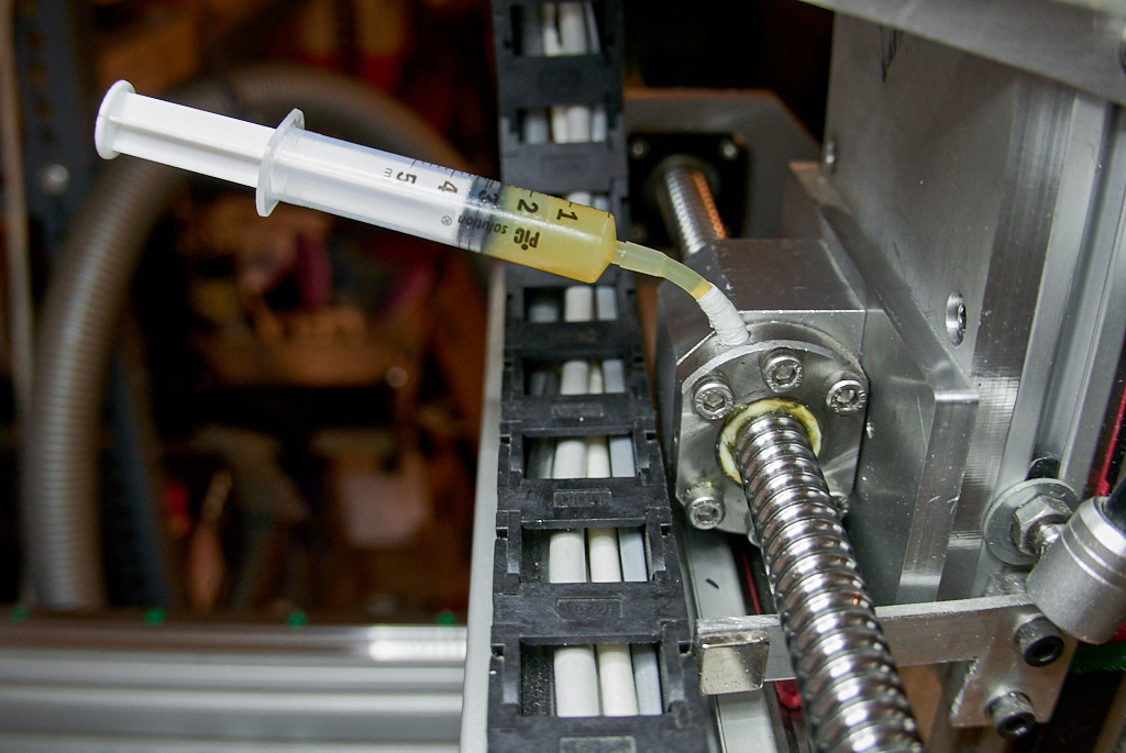
Even the NLGI 2 type I could quickly source in cartridge size (as opposed to bucket size) was fluid enough to be applied AND sucked in with a regular syringe. (This is a Mobilux EP2 for the record).

Syringe plus a bit of IV tubing plus a bit of teflon tape for a tight fit for the ballnuts.
Plain with just hand pressure for the rail blocks.
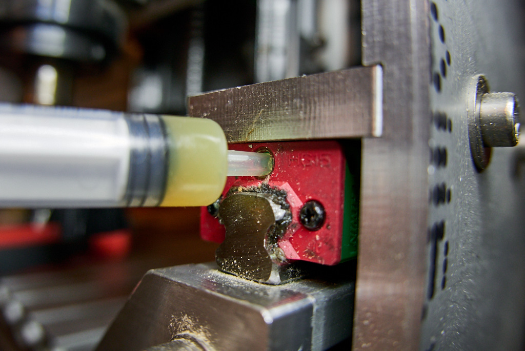
If grease comes out of the inlet while pressing the syringe, wipe and try again. The fit is not right. Add more teflon or apply more pressure.
If it comes out of the front of the ballnut or the front/bottom of the railblock, stop. The fit is right. The ballnut/block is packed with grease. Adding more may damage the seals.
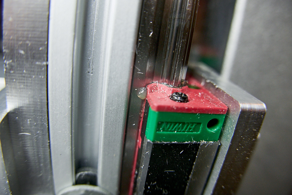
Close the openings with short screws. Done.
3 Likes
I had bought one of these Roland type blade holders a while ago and was brainstorming ideas for mounting it. I did not like spring or elastic band type of mounts, as in both cases pressure can diminish over time. I opted for a different approach: constant mass => constant force => constant pressure.
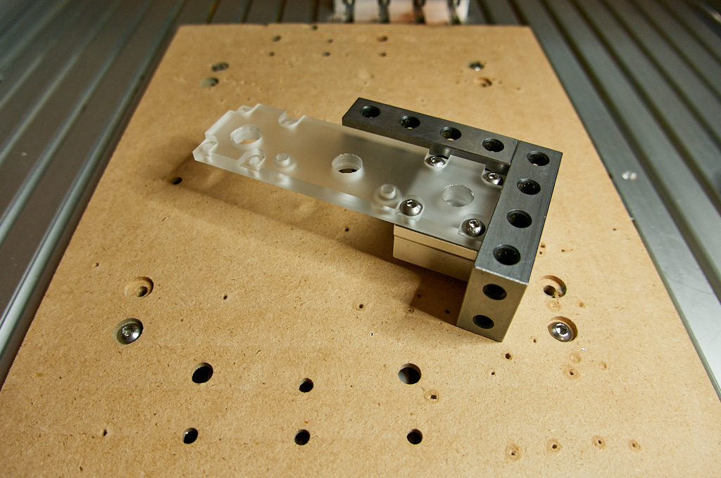
I had to make a holder adapter and a plate. Delrin and plexiglass was the available stock. Including some pics of the adapter machining, as this should have been machined on a lathe. Milling it kicked my… er… was very creative in terms of workholding.
Holding from 4 sides cause slim & tall can fly off.

Checking parallelism. Plus some washers to prevent the vblocks from tilting.

Facing to reveal bore, then checking concentricity.

Drilling set screw holes.

And here’s the Z plate.
Plus first linear block. I went for 12mm (SC12UU) for extra mass on the shaft.
Second block gets tightened after shaft slides through both.

Adapter is press-fitted on the shaft.
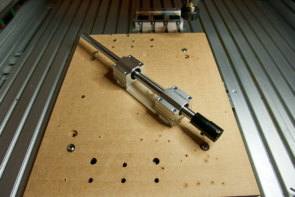
Plus shaft collar. Mounted and blade fitted.

So the idea is (after manually exposing enough blade to cut only through the sticker and not the backing) to lower the blade till it sits on the vinyl with pressure applied by the weight of the shaft. Then set Z0.
The shaft collar completes the floating trick. Even if the wasteboard is not freshly flattened, I can set the max acceptable float. Here it’s set at 1mm (i.e. it can handle upto 1mm “valleys”). Max “peaks” are determined by the travel between the bottom block and the blade adapter (and I let them pretty generous, around 10mm). I could do the same with the “valleys” but then the retractions would be slower. With the shaft collar 1mm clear, I set retractions at Z3.

First test was a 90-60-30deg triangle (i.e. 90-120-150deg change of direction). 150deg looking sharp!
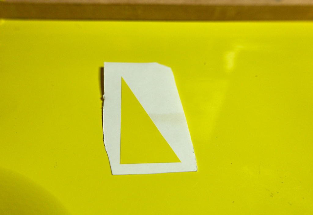
First real cut.

Tada!

Gotta find a better transfer tape though. Transfer tape adhesion was comparable if not stronger than vinyl adhesion. It should be the opposite!
PS. I used bCNC’s drag knife plugin to create the offset toolpath, directly on an imported SVG.
Funny thing, I was browing your thread regarding the Clearpaths yesterday, after having some binding issues with my current Z-axis. I was looking at something that would prevent my Z to loose steps/dive into the material. Had that happened three weeks ago which overloaded the RPM-governor of my Makita. (= no RPM control, max RPM only)
Replaced the Makita, and almost did the same one more time 
A VDF spindle would throw an alarm in such a case, but a closed-loop system would also do that - hence a peaked interest for a Clearpath system primarely for Z and Y-axis which is a single drive system.
Very cool drag knife setup, excellent job
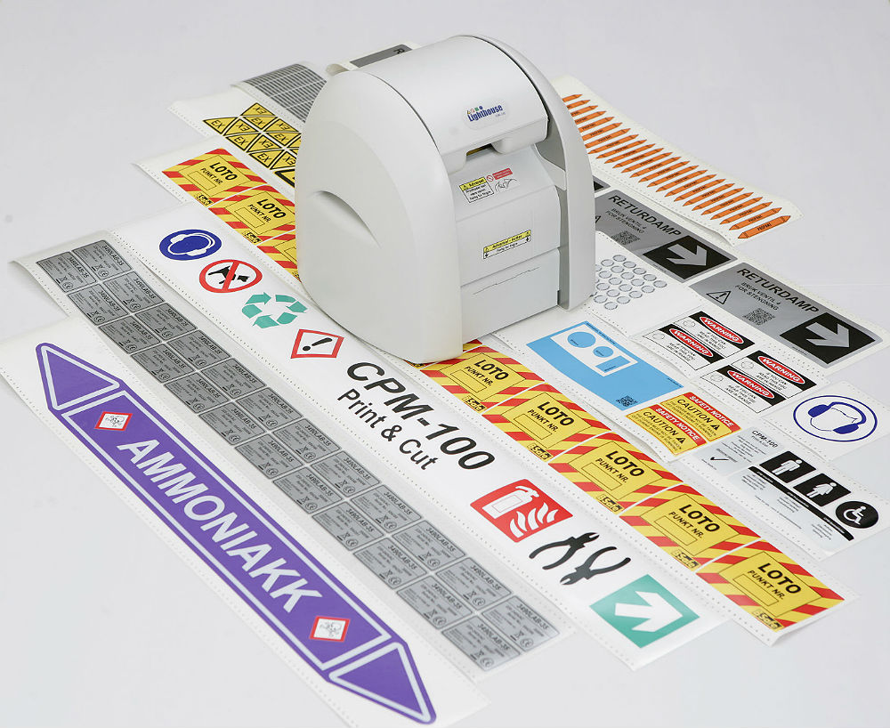
I would never be motivated to do a similar job, because I sell these babies at work
Multicolour Print and Cut
Here’s what my daughter would have said after looking at your stickers…
The blue boy could not get any sleep. He tried his earmuffs but the dog was way too loud. He opened the window and shouted “someone get rid of this dog, before I do”. Since he was awake, he decided to take out his recycling to the bin. Suddenly, a lightning struck the recycling and it caught fire. He could not reach for the fire extinguisher, but luckily he was carrying his trusted pair of pair of pliers and he managed to escape.
3 Likes
Wow, that is awesome looking. I did a similar idea but with wheels and 2020 v slot.