This is an adaptive toolpath (2D adaptive in this case as Z is fixed) out of Fusion360: 3/8" 2f tool, DoC 25.2mm, WoC 0.1mm, S 15800rpm, F 1000mm/min.
Why you’d want full DoC
- no stepdown marks
- uniform tool wear (as opposed to cutting with just the tip)
- better heat dissipation (more tool surface, taller chips)
Why you’d want adaptive
- you pick a WoC and Fusion translates it to a tool engagement angle
- the toolpath keeps it constant, no chatter due to abrupt change of tool engagement angle (e.g. from cutting a smooth curve to entering a tight corner)
- allows for high material removal rate
Adaptive & full DoC means you need to get to the target depth somehow. Ideally, if the stock is close in size to the part, you just lower to the target depth and lead into the toolpath from the outside. If the pocket is internal, you need to carve out your entry. In descending order of preference and ascending order of brutality: helix, ramp, plunge.
Also, adaptive is a roughing toolpath. For best surface finish, you may leave a thin wall and clear with a finishing toolpath (e.g. contour) afterwards.
Speaking of high MRR, this is the ultimate target, not high cutting feedrates per se. You’re trying to come out with recipes that are within your spindle’s HP, present no/minimum chatter (i.e. do not challenge your machine’s rigidity) and produce a high MRR. If you are going to make $ out of it. Or if you’re a sleepy dad 
EDIT:
I forgot tool deflection. Very important. Let me rephrase the above: You’re trying to come up with recipes that are within your spindle’s HP, present no/minimum chatter (i.e. do not challenge your machine’s rigidity), cause minimum tool deflection and produce a high MRR.
“Adaptive” is Autodesk’s terminology. Other packages that advertise high speed machining (HSM) will use it too. Others might call it trochoidal milling, which is a more accurate term.
A little trivia: trochoidal milling follows trochoids [from trochos (τροχός), greek for wheel]. A trochoid is the curve plotted by a point fixed in relation to a circle, as this circle rolls along a line.

1 Like
No problem, I love learning too. The turning point in my very short CNC history so far has been the moment I realized Fusion360 is free for hobbyists. If you want to dive deeper, I have just one suggestion as a start.
This.
Oh and btw, no sirs, armors or swords around here. Just sneakers, jeans and t-shirts 
1 Like
Thanks for the link. I just started using fusion the other day to solve a problem I was having on a job and love it, although the learning curve is pretty steep
Speaking of trochoids, here’s testing some recipes at full depth (10mm) in lieu of slotting.
Also took some time to organize the end mills from a pile of chaos to something more functional.
It’s one of these rare times you get to use crap you didn’t throw away. This is excess pick n’ pluck foam from a Pelican case.
3 Likes
i have some of that stuff. Thanks for the idea.
I am about to test 2D Adaptive myself so may I ask what your bit diameter (6mm?) /feed/stepover settings currently are?
Tool: 1/4" 2 fulte
Slot: 10mm (*)
S: 23800rpm
DoC: 10mm (the plate’s thickness)
WoC: 0.2mm
F: chatter started around 1100mm/min, I dialed back to a safe 700mm/min
(*) therefore the tool diameter to slot width ratio was 63.5% . It would be even safer to start at 50% (i.e. 1/4" bit & 1/2" slot) to make the curves smoother and chip evacuation better. I just pushed it over a bit to save some time. It will still take hours to finish all (6) plates.
The chipload that your machine can take is a “personal” thing. Each machine will have its own limits before it starts flexing one way or another (and therefore chattering). Unless you have a Haas
B-Carve’s rigidity (and therefore chipload capacity) is expected to go significantly higher once the alu plates are on. This is what I am trying to cut while using the plywood plates, so I am hitting a limit pretty fast.
1 Like
@EliasPolitis
Thank you! I understand that all machines are different and your setup provide me with atleast one data point
No Haas in my shop, just a diy CNC-rig with MDF gantry & SBR16 rails.
In alu I currently run 1/8" bit @ 1400-1800mm/min and DOC 0.2mm with pretty ok result despite it not being truly solid/rigid.
CAD/CAM is Easel up untill now but I am slowly migrating more and more over to F360 hence my interest 
Inkscape & jscut till I made the switch to F360 last fall.
I struggled initially with F360 and due to very limited time to play around it have taken me a while to feel proficient enough to make the leap 
That was interesting… I got a couple of freezes mid-job. I checked out RPi’s dmesg and found a bunch of crazy USB error messages.
Up till recently, the physical layout was X-Carve, X-Controller, RPi. Now, in order to save same workbench area, it’s X-Controller, B-Carve, RPi, which means that that randomly picked USB cable was crossing behind the machine to reach the controller. It seems that we were hit by the EMI trolls! (Could it be the two Y motors? )
I found a proper cable with a ferrite on one end at work. That worked.
Production resumed.
2 down, 4 to go.
5 Likes
Nope, the new USB cable was not enough. I had another disconnect. Bypassing the X-Controller’s USB pigtail did the trick. It seems I was not the only one.
I also took the opportunity to route the USB cable towards the back. All it took was filing a little notch on the top panel.
Rear Y plates.
2 more to go.
5 Likes
It seems that the USB bulkhead connector has been giving several people issues lately.
I recently had to replace the cable and attached PCB (start/pause/cancel buttons)
1 Like
First Easter break, then an incident (fortunately unsuccessful) at my wife’s school got us watching 13 Reasons Why at nights.
I’m planning to make some time for the X plates this week.
was your design based on a grabcad model? Bc I found one the other day that seemed to have some resemblances.
I did research several models as mentioned in the beginning of the thread here , but was not happy with everything they had to offer. So I kept some clues and came up with my own design.
Here was the main idea:
- I settled with 15mm rails and 16mm ballscrews
- simple setup for both X and Y, thus end plates everywhere (as opposed to boxes and braces)
- therefore the ballnut mounts needed to be coplanar to the rail blocks
- for the X everything is bundled into a custom C beam
- for the Y after several iterations I came up with the solution of having both rails and ballscrews bellow the work surface (a) for maximizing X travel and (b) for better dust protection
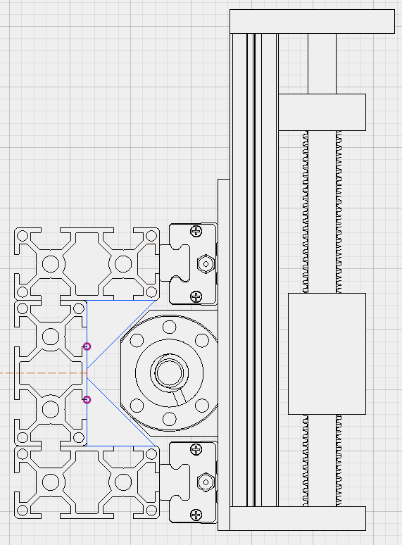

These two snippets are the essence of this build.
Btw, I’d be curious to see/compare the grabcad model you discovered if you have a link.
1 Like


