
It looks great!
Awesome!

4 Likes
Congratulations that really looks like a very capable machine.

really interesed to hear your first impressions and things you would have done differently in hindsight. if any 
Hey everyone, thanks for the stamps and everything
@anon68752607 some preliminary testing has shown that compared to my X-Carve double material removal rates are possible. When I started I was aiming for 30% time savings. It now looks like 50% and I am confident it can be pushed even further with appropriate tuning of toolpath parameters. Considering that the #1 goal of this build was “sleep more”, this only makes me happy.
One thing I would have done differently which has also been mentioned earlier in this thread: I would get the ballscrews with their ends premachined and ballnuts as a kit. The cost savings were not worth the time penalty. It was almost a couple of extra months of waiting for shipments and trial & error.
Design-wise there is room for one more thing that I have been thinking lately. I might leave this for a sequel… Building B-Carve Season 2: The Return. We’ll see. The script is there, I will have to talk to the director and producers 
2 Likes
Get all the bugs worked out then start making kits!
1 Like
…and wasteboard strips.

End of Season 1. Thanks for watching. Also thanks for the support and the ideas. That was fun
2 Likes
We want some videos of that thing shredding before you close out the season!!!


wipes drool
Very, Very, impressive.
But personally, I need that big red button a little closer to the front of the machine.
Just sayin.
@EliasPolitis Awesome work. I’ve just build myself a new machine using the x-carve too, and I think my t-track is similar to yours. How did you attach the mdf to your t-track? the m5 pre-insertion nuts i normally use are too small, and therefore useless.
@JanVanderlinden
I may have used the red button a couple of times in the past year and a half.
Ever since I hooked up the gamepad I keep this close and whenever needed my left thumb finds the button that is assigned to “PAUSE” [which in bCNC toggles between “!” (feedhold) and “~” (resume)] without even looking. This way I can prevent something bad pretty fast and in case I correct it, resume from where I left. Red button=start over.
For instance when milling the holes for the narrowest (middle) wasteboard strip I realized the dustshoe was going to crash one of the clamps: feedhold, release clamp, clamp behind the toolpath, resume, mill “problematic” hole, feedhold, clamp again in original spot, resume. Btw, clamping in 3 places allows you to move the 4th one without moving the workpiece a bit. Kind of like climbing by keeping 3 points of contact while looking for a new 4th.
@BrendanCoutts
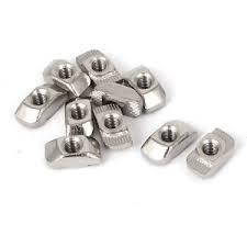
The whole build uses 3030 T-nuts like these in various hole sizes (M5 for the wasteboard).
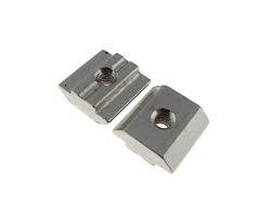
The only exception were the bed-to-frame nuts. In that case I used this type of post-installation nuts, which mount very fast (and very clever, they self align and they do not need to be fished) . Some places call them hammer T-nuts, some swing T-nuts. You mount them on the original part with orientation parallel to the slot of the destination part and they swing and lock at 90 degrees once you tighten them in place.
Amazing looking machine, quick question, how long can you run the Makita spindle without it getting hot, I have the same router and I have always been a bit reluctant to use it for long carves as I worry it was not built for that? thanks
I also use a Makita RT0701 router, at speed 1 and 3hr carves the metal base is barely warm.
1 Like
Hm… this is not an easy answer.
There’s heat from the spindle itself and heat from the workpiece that can transfer from the endmill back to the spindle. There are several factors to consider. WoC, DoC, feed, speed, material hardness. They affect the Watts required for the cut… and also affect the chip thickness which is what takes heat out of the part.
Also, being an air cooled spindle, the higher the RPMs the higher the airflow. On the other hand you cannot rely on cooling by bumping up the speed, since higher speed => higher SFM => lower chipload => risk of rubbing => higher feedrate to compansate => higher MRR => higher wattage => hotter. Looks like a vicious cycle.
Even the material and shape of your spindle mount will affect heat dissipation (for better or for worse).
But then, guess what… having a not so rigid machine (*) has one advantage! It will prevent your router from cutting at high wattage, it will flex and cause all sorts of chatter if you try to push it. This will allow you to cut at lower wattage for hours non-stop without getting (too) hot.
I’ve cut for 5hr and could still touch the spindle after.
In any case, get an extra pair of these:

and use the best spindle overheat protection system available out there. This:

(*) Not to get misunderstood, X-Carve and especially gen 2 X-Carve is pretty capable. Read this as “not as rigid as a CNC mill”.
1 Like
Thank you so much for the detailed feedback, it was very helpfull
1 Like
Here’s a quick tip for people using hall effect sensors (@RobertCanning , @ErikJenkins, @StacyBoncheff you might want to try this).
I was wondering whether it would make sense to face the sensors with the south pole of the magnets in the orientation shown below in order to make the exposure to the north pole as sharp as possible.
I sent Kevin this photo

and this is what he said:
The Hall-Effect sensors I’m using are unipolar sensors, and are only sensitive to the North pole of the magnet.
If you approach the sensor with the flat north face of the magnet parallel to the sensor board, it will trigger when the field reaches a certain strength. (board and magnet are parallel). However, if you PASS the board with the magnet PERPENDICULAR to the sensor board, with the south face approaching the sensor first, it will RAPIDLY trigger the sensor in a very short distance of travel as the edge of the magnet PASSES the U1 sensor chip, and the chip is exposed to the north field on the back side.
OK, so looking at your photo, the arrangement is ideal. If the north side is facing the sensor (in the position as pictured), the sensor will trigger at a certain distance depending on field strength. If you flip the magnet around, the sensor will not trigger until the magnet passes over U1 on the board, exposing it to the north field on the back side of the magnet. This will provide very positive triggering in a very short, repeatable distance. It is the configuration I prefer. But you are free to experiment and figure out what works best for you.
This is maybe on the OCD side, but it does not harm to get the best repeatability out of your machine. ![]()
Note: Switching from approaching the PCB to passing over the PCB, you need to make sure of two things:
- you might need to adjust the magnet higher so it clears the PCB
- you might need to adjust the sensor’s position a bit further from the axis end so that the moving part (X: carriage, Y: gantry, Z: spindle mount) clears the axis end
4 Likes
For reference, here is graph that shows the effect of a cooling fan on the shaft of a Kontronik model airplane motor. This graph shows the coling capacity vs motor power. RPM has a big influence on the cooling capacity.

