
There seems to be some confusion regarding proper grounding of power supplies, and is a somewhat “black magic” topic for many people. What is 0V? What is Ground? What is DC Common? Aren’t they all the same thing?
No. No, they aren’t the same. They are the same voltage, but they are for very different things. They aren’t interchangeable, and cannot be used as a single large node.
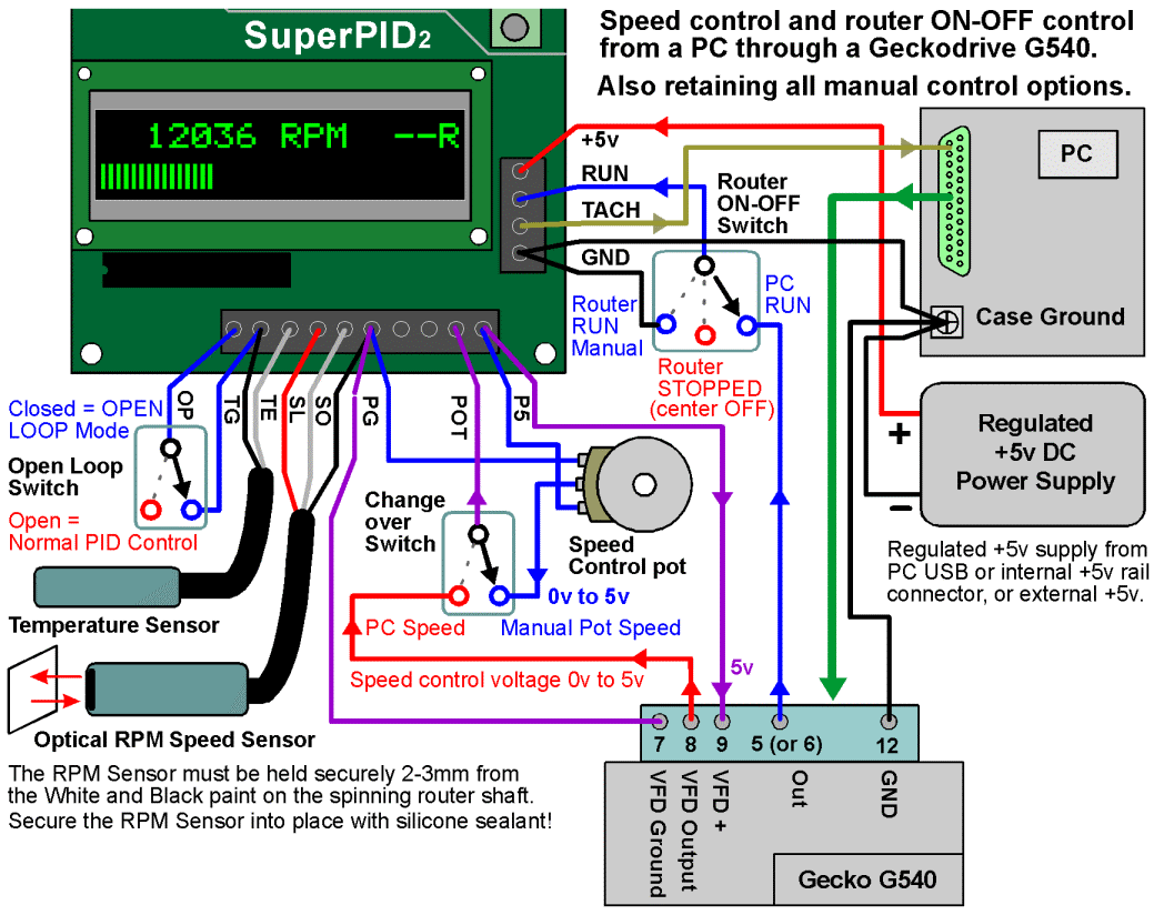
What made me decide that writing this little rant/blog was necessary was this schematic on wiring the SuperPID. I know it’s a very busy schematic, but look specifically at the black wires on the far right going to the 5V power supply minus terminal, the PC Ground, and the SuperPID “GND” input. The problem with this circuit is that the PC ground screw is meant for noise immunity, for filtering, for safety, and is supposed to be an earth voltage reference to hold the 5V power supply referenced to earth.
Especially for circuits that connect to an outlet, “0V” is typically regarded to be the voltage of the earth. It’s a reference. That’s a big part of why we use earth ground in circuits. When you connect a two terminal power supply minus wire to earth ground, such as on a PC supply case screw, you are forcing that power supply to reference earth ground for its 0V, or DC Common, voltage. This is important because without the ground reference the +5V is only 5 volts higher in potential that its own 0V wire, but is floating with respect to the rest of the world. Measuring an ungrounded power supply 5V against earth ground might be 2V, it might be 8V, who knows? So to prevent accidentally giving your device an unknown voltage, you ground it. Got it? Good.
Next, Ohm’s Law. V = IR. The voltage across a resistor is equal to the current through the resistor times its resistance. A huge part of why using ground wires to carry current is unacceptable is because wires are resistors. In the schematic above, up to 200mA of current will flow FROM the SuperPID, TO the PC case screw, and THEN TO the 5V power supply minus terminal.
Why is that bad?
Because it ruins the whole freaking reference.
Say the resistance of the wire is 0.25 ohms, and then say the current for controls is 200mA. That means the voltage drop from the SuperPID GND terminal to the PC case screw is 0.05V. Then say the wire from the PC case screw to the 5V supply 0V terminal is another 0.25 ohms, meaning another 0.05V drop.
“5mV, pshh Nathan, you’re freaking out over nothing.”
No I’m not!! What if it was 4A?? Suddenly it’s a 2V drop! And even at just 200mA, this means the 0V at the 5V supply is actually negative 0.05V when referenced to earth ground and the positive voltage is 4.95V. These kinds of imbalances can really f*** with a system with multiple power supplies and cause data loss and even hardware damage, if not fires. I literally just last month got called out to a GM factory where a huge machine was catching on fire because their power supplies weren’t grounded properly.
I know it’s complicated, but it’s important. Just because it’s low current is no excuse for negligence.
What’s the proper way to do it? Run your power supply + and - wires directly to the device you want to power. Run a second wire directly from your power supply negative terminal to earth ground. If there’s no current going through your earth ground wire, there will be no voltage drop.
The end. harumph.