
I ran my first carve on the X-carve today (750mm) The calibration process went fine and everything seems to be working properly. The problems is that the resulting carve is really bad (I can’t figure out how to upload a photo). The text looks nothing like the preview and has islands of wood in the middle of the areas that should be routed out. There are a couple of spots where it looks like the router bit didn’t lift high enough and routed channels where there shouldn’t be any. I did calibrate the z-axis with the z-probe and double checked the material thickness. The belts are tight, (can they be too tight?) and the idler wheels are all adjusted so they are tight but can be moved by hand. Any suggestions would be most welcome!
How do you upload pics here? I couldn’t figure it out
When you are typing your message/reply, press the button with the red circle in the image…

After you hit upload, wait until the image is in the preview pane on the right before you post the message.
1 Like
Ah - here is a pic of the first carve fail. Forgot to mention I used the setting recommended during the calibration, including the 1/16" bit.

Hi mate, here’s a good thread re calibration:
It goes over the belt and wheel tension plus a whole bunch of other useful stuff!
Thanks very much - This looks very helpful!
John, it looks like your steppers are “loosing steps”.
What feed rates / depth of cut did you set Easel to do?

With my issue, it seems the left Y axis and the right Y axis aren’t operating smoothly together. All the v wheels have been checked and the belts were undone and redone…X axis is perfect as is the Z from what I can tell…argggh
Hi James, have you gone through the calibration process’ on the videos on link I gave above? I was having similar issues to yours and they helped a lot. Turned out my issue was too tight V-Wheels, and to tight belts.
Not sure what the issue is as of yet…I’ll check out those videos. Seems the right side y axis moves appropriately, the left side y axis is a bit sluggish. X and Z seem good…
Are you sure the left side Y motor is actually getting power? And the power wires are flipped for one of the Y motors?
Xcontoller…
That sounds like a possibility…seems the left side is “dragging” some compared to the right side…
What do you mean flipped?
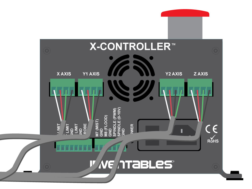
You’ll see the black and green wires on this image for the Y2 motor are swapped. This is using the X-Controller, if you’re using the old electronics, the principle is the same.
1 Like

Just make sure you haven’t already flipped it on the motor end (if that’s possible with your kit, I think they changes to plugs instead of bare wires at some point).
Nice neat looking job btw.

No worries, do still go through the calibration videos in the link above though… it will save you a lot of grief, and $$ in material, if you do.
2 Likes