I’ve tried this inlay several times and keep getting similar results. I’m not sure if its in the software or machine side. Here is my process:
- Trace the image using Easel
- run the inlay app using .125 bit size with a .003 tolerance.
- Make a copy of the page. (I run all carving from the copy to keep the original as backup)
- delete everything but the design I want to carve out, And then carve.
- copy the inlay from the original page (I’ve actually tried "undo"ing back to when I deleted the inlay from the page I was working on, so this isn’t the issue.
- carve the inlay. (I’ve tried several different materials and speeds and get the same results.)
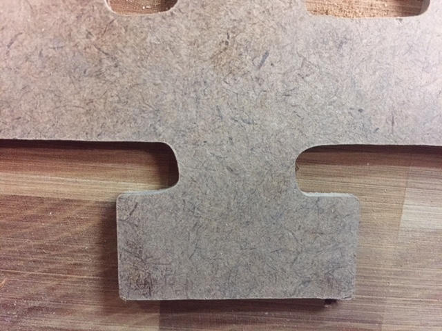
So far the carve is consistent. I’ve ran this three or four times and the negative space carve looks to be the same every time. But, the actual inlay seems to vary. Rounded corners where the initial carve had straighter lines.
The fifth and sixth pictures are swapped, but other than that, the first picture is the space and the next is the inlay. Hopefully you can see how different they are from each other.
thanks

This is typical flex in your system, you are simply going too fast / too deep / too hard at the moment.
If the system flex the bit will “drag” behind the actual path and cause corner deviations like this.
I tried slowing down and shallower cuts. Interesting thing is that the rounded corners appear in each of the multiple cuts. It’s not like the first pass is different than the second.
Also, it’s strange that the initial carve seems fine. It’s just the inlay that isn’t working. Similar material, speeds, depths for both.
Here is another try. The first is the original carve. Second is a 1/8 piece of fiber board ran on MDF setting in easel. Third is the same material at 1/2 the suggested speed. The inlay cuts are identical, but don’t match the inital cut.
As mention above I am thinking something is loose. V-wheels not quite right or belts not tight enough. Loads for inside cuts are a different than outside so that may be causing the difference in the two. Have you tried swithcing to a raster cut for the female side. Might make a difference.
Most CNCers will assume it’s the vwheels on the Z-axis causing this problem. I discovered on my system that it’s the Y-axis rail eccentric nuts that weren’t tight enough. It caused the exact same problem you’re seeing. When those are too loose, the gantry can twist when it plunges into the material causing those deviations. Tighten up the ship and she’ll sail right through those cuts with exactness.
Thanks for your help. I’ll give it a try and report back.
I had those inconsitencies for a while, then the left motor did not work properlly (at all I think). I called, and the lady recommended to switch the plugs for the motor from Y1 to Y2 and vice versa, what I did, woprked well, now I changed them back and from that minute on the machine workes like a charm. But it began with these small inexactnesses. Probably there was a loose contact in the plug of a motor. The cables were / are tight in the plug, so I recommend to check all these, the cable connections and the plug itself.


