Hello!
I recently re-calibrated the machine, all works fine except that it continue to cut the pieces with a very high tollerance.
For what I can say, all the screws are tight, belt are balanced and well tensioned, wheels are ok. I calibrated both X and Y axis with a long rule on a scale of 600mm with a 0,5mm routerb bit and as far as my eyes can see I have setted them dead perfect.
Now on a recent cut I noticed that I have near -0,85mm of tollerance (on both sides of the work so is more than1,6mm of tollerance on the whole design!!) and for what I need to machine is really unacceptable.
I have really tried everything I know, the machine look also pretty squared too. Am I missing something? Don’t know what else to do.
You should do better than that.
What is the software chain you use? Software should take your bit diameter into account when calculating the toolpath. If your definition is 1/8 and you are milling with a 1/16th bit it will be off.
Have you checked the wheels, if the inner ridge in the wheel does not match the washer thickness you can get play in the wheels. Occasionaly we get a post about wheels being off tolerances, the ones supplied with my machine work perfect. The 4 Openbuilds wheels I bought last week have 0.4mm play which makes them useless.
Can you post your machine settings?
Hello,
My machine is the 1000x1000 version, I have only made the V-Wheel mod, the X axis stiffening mod (with the steel bar on top), Z axis mod, and replaced all the pulley grain with screws. No wheels replaced, all of them are stock.
All my drawing are made with Rhinoceros 4 and 5, all CAM process are made with RhinoCAM14 (where I work) and RhinocCAM16 at home but only for 3D cutting.
I only use 3 kind of bit, a 0.48 for center line, a 6mm (which seem to be 5.79mm measuring the tip with a caliper) and 8mm bit that is 5.82mm on tip, that I only use for 3D work where I don’t need all that precision.
In fact I was cutting a guitar neck template a couple of hour ago, with a nut of 42.8mm (resulting 42 pretty much), and the last fret of 55.6 (resulting on 54.25 pretty much).
Can you try a 50x50mm square from Rhino/CAM and the same size set up in Easel only? (Two jobs, two workflows)
If they both exhibit the same actual size then the workflow is correct, if Rhino/CAM is smaller than Easel then I suspect Rhino/CAM havent performed its finishing pass?
Hello,
What kind of bit you suggest me to use? And the job should be made inside or outside of the square?
I have to say that basically I have used Easel just to calibrate the motor, nothing more. Well, in fact is the method I know to calibrate the motor.
Doesnt matter. If two separate workflows produce the same measurable result then the culprit is not on the design side - but more a calibration/mechanical issue. (Backlash / Slack / Tool deflection etc)
If Easel produce one size and Rhino another size then there culprit is within the design/CAM settings.
I’ll try. Let assume that both test give me similar results but the dimension are both incorrect, what you suggest to do? Recalibrate untill I have perfect sqare or still need to go on the long straight distance?
I found one of the bits I was using caused my calibrations to be out. Apparently I must of hit one of my holddowns. Change your bit and try again to see if it improves.
Well, I’ll answer both @PhilJohnson and @ErikJanssen
Yes, my current bit is a little dull, I only use it to cut MDF. The 6mm bit I have only do this work. For woodwork I use the 8mm.
Anyway, as said, if I found that on long straight distance the tuning is perfect but square, rectangle and circle are not, what to do? Recalibrate 'till square, rectangle and circle become perfect?
A dull bit or too deep cut can introduce side forces that makes your bit dig into or push out of the material. In that case it will not be square or round just by flexing the bit.
What if you draw a 50mm square with a pencil, that should be square if cutting forces are the cause.
If you move your X axis forward by jogging at slow speed, is the gap to the front of the machine equal on both left and right side, and does that stay the same when moving 1mm back. If so check belt tension and pulleys. Also measure the amps on the two Y motors.
Grab the spindle and twist it in any direction you can imagine, if you hear a click somewhere one of your wheels has too much play or the set of wheels are not working together in the same plane.
Just observe what you machine is doing and it will tell you where the difference comes from.
Mmm ok I haven’t had the time to run some test, but reading the whole story I think is the time to a complete rebuild? I really wanted to upgrade some parts.
Well, while you make me think about Y axis position, EVERY time i turn the machine on I need to ‘square’ the Y axis with putting 2 identical cube in front of the machine and pulling the axis against them to make sure is squared.
I also noticed that the right side of the machine is usually a little bit forward than the left side, of about a millimiter or less.
I can assure that the extrusion is square but never found why the Y axis act like this and I always have to ‘square’ it.
I think your answer is here, if the machine changes squareness when powered down it means there is tension in your setup.
The length of the X makerslides may differ or your stiffening method mounts them into a shifted position against each other. Loosen the bolts of the stiffening bar and slightly take of the tension of the bolts in the Y gantry plate. I assume that you measured the Y squareness diagonally. Verify the position of the X beam in the Y gantry plates, measure the distance on the back. Now your Y should stay equal on both sides when joging back and forth. Start tightening everything up and see when the behaviour changes. Solve this and your machine will stay square.
I have to check it before squaring the machine with the 2 block or after? Because before, I certainly know that the axis is not parallel
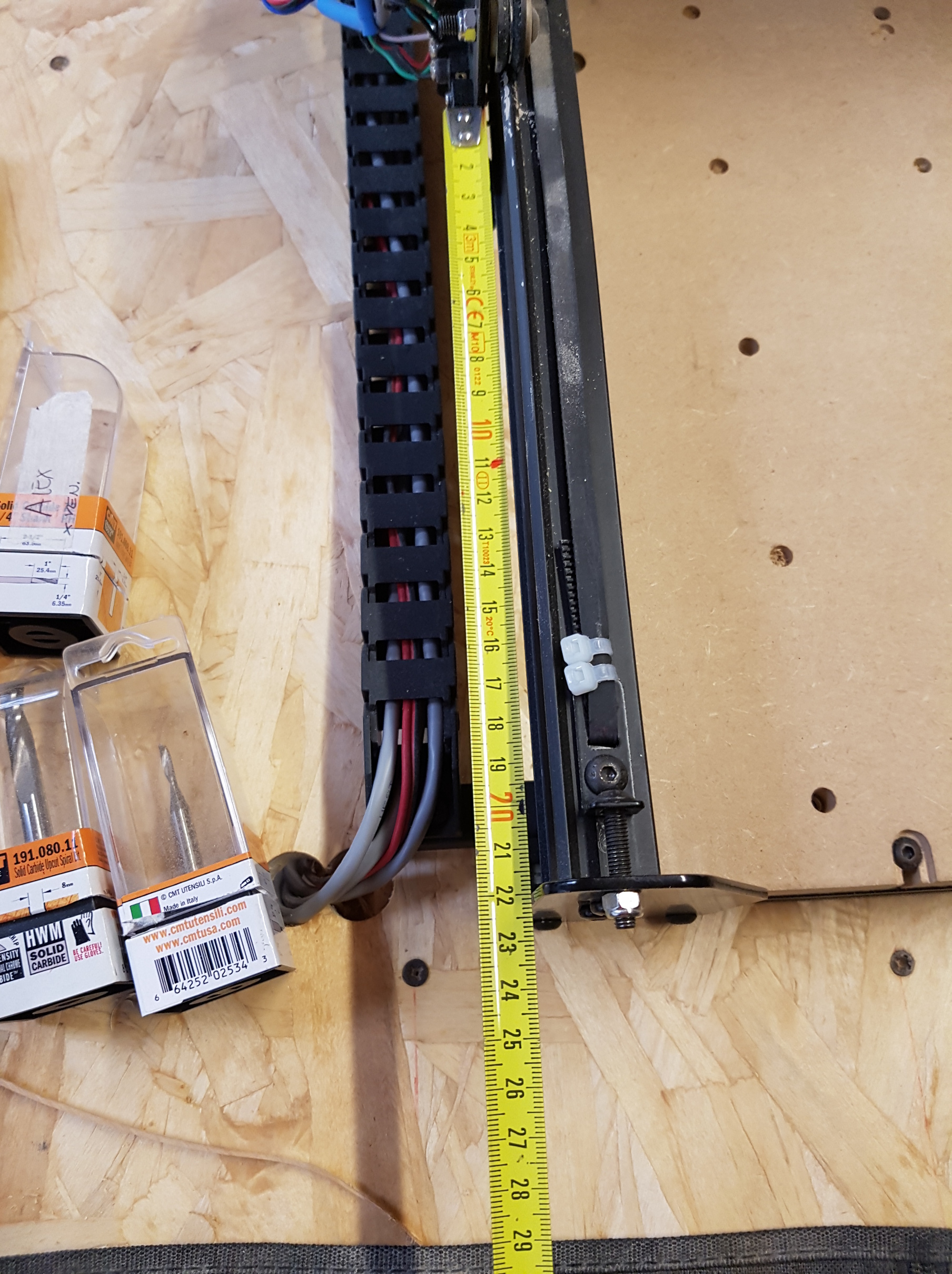
This is what I have with the machine off. I simply pulled the X axis against the rule and seem like the left side move more than the right side.
Right side.
Left side
Now that I have squared it, I have 22.2 form the left side and 22.2 form the right side.
62.3 on left and right back sides, so I assume the machine is pretty squared, right?
If I move the machine back and forward with UGCS it move correctly, the distance is the same on both sides, front and back
Engraved 3 square of 50, 75 and 100 mm and 3 different circle with not perfect diameter (41, 64 and 81mm) and all look almost perfect, at least with a tollerance I can accept.
I feel kinda lost! I’m pretty damn sure that if now I cut a neck template it will be wrong.
Thanks for the pictures. Next step is to measure from the left back corner to the right front corner and compare this with the distance from the richt back corner to the left front corner. This should be identical. This needs to stay identical so you need to fix the machine to the table.
You can start by bolting the back to the table and then slide the front 20x20 beam in such a way that the diagonal measurements are identical. Then attach bolts at the front.
Not so easy to do this alone but seem to me that I have 137.5mm from left back to front right and 137.5mm from right back to left front.
If your machine engrave within acceptable tolerance but fail to do so when carving then you may have tool deflection which is a function of sideways loads when cutting. Engraving is a light load and may not exhibit much in terms of tool deflection.
What kind of dimensions do the squares and circles exhibit if you actually carve them out of some scrap wood?