
Nice cat! That one would be great for daysailing in warm weather. We currently get our sail kicks from a trailerable 22 foot single hull cruiser. I have gotten a leash on my lust for a Telstar 28 trimaran, but still susceptible to any visual or text references to one.lol
Strips are not a problem. I can probably cut a couple dozen at a time by stacking boards on edge on the sawmill and cedar trees are abundant here. Was thinking a cnc router would be great for mass producing the other components and putting together a kit. Have since come up with a lot more ways that would probably utilize the waste cuts from the mill better. I hate to see it go to waste. Some kind of boat-thing is definitely on
the to do list. Anything under 14 feet with no motor requires no registration, so I’m looking at that if I market something that floats locally. Lots of lakes around and I think something lightweight, economical and storable might work. A cat that folds in half for room and stability in use and ease of transport and storage? haha
Hi i jump direct to 1000 x 1000, and its short for me, now im going for a 1800 x 1800, any one have try this upgrade?
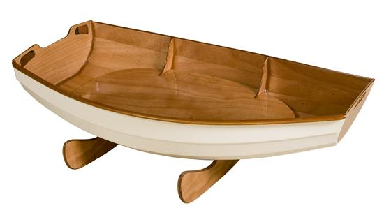
Funny you guys should mention boat building. John Harris at Chesapeake Light Craft gave me permission to use his DXF file for the Eastport Pram. Without giving away the design, I’ll be showing how to manually index the parts on a XC1000. When used 1:1, it makes a very cute boat just under 8’ long so it can be cut out of sheets of plywood. At 2:1, it makes a 4’ long coffee table or cradle.
http://www.clcboats.com/shop/boats/boat-plans/sailboat-plans/eastport-pram-rowing-sailing-kit.html
http://www.clcboats.com/shop/boats/rowboats/dinghies/baby-cradle-pram.html

Yes, she’s got a cute little high aspect ration lug that I use to scoot back and forth across Green Lake in Seattle. I also did Duck Dodge on Tuesday nights on Lake Union last summer. Her big sister, the Passagemaker has a gunter-sloop rig, which I can’t wait to build…
The mast fits into a socket in the forward thwart. The mast step butts up against the forward bulkhead so that you have both silicon-bronze screw and wood-flour epoxy fillet strength to transfer the load to the hull. Super simple, super sexy!
Ironically for being on CNC forum, I pride myself on being a plans builder. I want to be the one that cuts out boat parts with MY carver, not pay someone else to do it. Plus, plans are under $100, where a CNC kit costs over a thousand.
I got myself into a little trouble on Lake Union last Spring. I capsized and couldn’t self-rescue because the gunwales were below the waterline, even with all the built in buoyancy. I had to get pulled out with the halyard of a large sloop. My fix was to buy a couple of buoyancy bags for Optis and wedge them into the lightening holes.
This is the Passagemaker, the big sister to the boat I’ve already built. She’s got a sliding gunter rig, which should be fun. With the jib, I should get much better upwind performance. I’m building the version that you cut in half once it’s structural. It’s a cool design that incorporates a plywood and cardboard sandwich for one of the bulkheads, so the saw follows the softer cardboard.

That decision was made by Edward Ford, who designed the initial machine, and the X-Carve’s direct predecessor, the ShapeOko 2, using Bart Dring’s Makerslide.
The initial machine design was severely constrained by volumetric considerations — one design goal was to fit it in a USPS flat rate box — I suspect the SO2 and XC are similarly constrained by weight. Also, at the stock machine size, the base shouldn’t be subject to that much force, so the 20x20 is a suitable choice.
Yes, but the 20x40mm extrusions would add more ridgidity to the base. This would make for a sturdier machine bc its foundation is stronger.
Just saying.
I disregarded the stock table bc it is not very ridgid and I am not using these pieces at all. I have based this decision on the Cubed Root Rule for stiffness. Think of a guitar brace, the taller the braces are, the more stiff the soundboard is. I upgraded the foundation of my table to the 20x40 for the extra stiffness
I would also replace the cross bracing with 20x40 as well. If you want to use the 20x20, use six 20x40, 4 of which run parallel to one another (could get away with 3) and two perpendicular to the others on the ends.
Use the 20x20 to tie the 4 parallels together. Keep the 20x20s as short as possible, they will have the most deflection.
This setup will stiffen the entire wasteboard. Just using the 20x20 in the center will only stiffen the perimeter more. This will allow the center to sag, possibly even more since the center will technically be floating 20mm above the surface of the support table. Adding the 20x40 across the center of the wasteboard will be necessary if you widen the perimeter supports as well.
Don’t get me wrong, IF the supporting table is sturdy enough, the 20x20 will suffice. Just keep in mind that the 20x20 will be using the support table more than a 20x40 to obtain the same amount of stiffness. This will require connecting the two together to act as one unit.
Michael Grigg: Could you provide a drawing of what you are describing? I’m having a hard time trying to visualize all the cross bracing you describe. Thanks.
Here is a quick free hand sketch.
The long pieces are made up of 20x40 extrusions where as the short pieces are made up of 20x20 extrusions. I still recommend using 20x40 extrusions for ALL of the base but this process will add more ridgidity over the stock base. And allow the use of the 20x20 extrusions.

This method does require more connecting hardware, but that’s a given bc there are more pieces and more intersections to stiffen up.
Ok, I am about to throw some numbers out, these numberes are used as EXAMPLES only and do not reflect real world measurements.
Take two pieces of 1000mm extrusion, a 20x20mm and a 20x40mm extrusion. Each piece is tested on edge so that the 40 is vertical. The 20x40 extrusion will deflect 1/8" in the center. The same length of 20x20 may deflect 3/8-1/2". (Rember made up numbers) The taller of the two pieces is significantly stiffer is the point that I am getting at.
The only way to get the 20x20 more stiff is to shorten its lengths, so that there is not as much distance to span for the deflection. This will keep the deflection as a minimum.
For example, take a stick 12" long. Snap it in half, not to difficult. Snap each new piece in half, little more resistance. This leaves you with four 3" pieces. Now try to snap these in half, not so easy. The delflection is what allows the item to bend, eventually snapping. If the deflection can be deminished bc stiffness is increased, the part will not bend. The way to increase stiffness is to either make the piece taller or to make the piece shorter. The deflection is directly related to the length of the item.
Check out Angus’s build. His set up is the method I would recommend following, of course this can be scaled down to a smaller machine as well.
I only give the addition of using the 20x20 extrusions as an idea of what someone can do with them in case they have them extra. If I was ordering new parts, all of those would be the 20x40.
Hope this helps.
Thanks. That helped a lot. I agree that 20 X 40 extrusions for the entire base is probably the way to go.
This is exactly what I did as well.
I am Thinking the 20x20 will make a good enclosure frame for a 3D printer. That’s what my XYZprinters enclosure frame is made of.
i think build the size you want
Currently in the initial phases of building a 60" X 66" unit out of rectangular steel tubing that will have rack and pinion drive with belt reduction. About to start the tedious process of installing inverted angle iron on the frame to run v groove bearings on. Assuming that getting those right will be the most critical and time consuming step, but I’ve been wrong about other things. haha
Awesome! Good luck, I would love to see you progress!
content://media/external/file/23081
Getting the top rails straight and parallel was a bit of a challenge…used 28 gauge annealed wire stretched over the top for straightness guide…fresh outta piano wire. haha