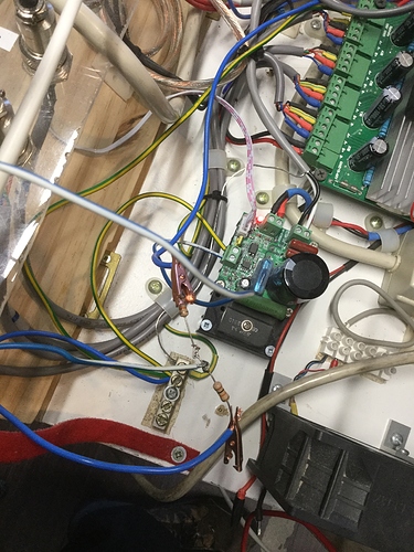
Good morning everytone. Hopefully someone with the know how is monitoring. I have a quiet cut spindle. The documentation (as far as I am concerned) is a bit lacking. I also have a TB6600 board for motion control. The TB6600 board has a 0-10V PWM output. The quiet cut spindle speed controller has a PWM input, however all the documentation states is that PWM is 5V. My question is what is the proceedure to connect the two to work within Mach3. The TB6600 gives a varying voltage (anywhere from 5 to 9.8V) when the spindle is activated in Mach 3. I do not wish to smoke the speed controller by applying/connecting these two as I believe was intended. Can anyone help out with some answers? I dont NEED to run the spindle through Mach3 but it would be nice.
Thanks in advance
Russell
When you put two equal value resistors in series the current that flows in each resistor is the same (minor variations due to resistor tolerance occur).
For two equal value resistors the voltage drop in each resistor is the same, so you in effect divide the voltage in half when you use the following circuit.
Awesome Larry, Thank you. I knew someone would have the correct info for me. One last “dumb” question. I believe that arrow after the second 10K resistor is ground Yes?
Thanks again
Russell
That is correct, GND / 0V reference
Larry I tried that. It seemed to work too well. All I get after the resistor is 1.7v. I even tried to step it down with some 8.2K resistors and not much difference. Any sugestions? I do have a nice assortment of resistors and was going to just keep trying lesser values until I maybe got something to work.
Thanks again
Russell
Good morning Angus, Yes my dvm is set to DC. I did check the input voltage and just on the other side of the resistor I get 9.8v
Thanks
Russell
The general formula for the multiplier of a voltage divider is R2 / (R1 + R2). If you multiply your input voltage by that value, you’ll get the output.
Are you sure that you’ve got your resistor values right? Is it possible that you’re using resistors that are wrong? Have you measured your resistors by themselves to see if they are good and the value you expect them to be?
I took the second schematic down. There’s something else wrong with this test.
I appreciate the help guys. I will take pictures of my TB6600 board and the way I understand you showed in the diagram. I will also take pictures of the resistors. I did triple check the colors against an online resistor identifier as well as my cheatsheet hanging on the wall. As for the speed controller it is the Inventables speed controller. It wont be for a couple hours yet as I have a few things to do prior to getting back into the shop but that will be the firsat thing I do.
Thanks again.
Russell
P.S. here is the speed controller https://www.inventables.com/technologies/spindle-speed-controller
Here is a picture of the board I am using (middle Pic is best) 4 Axis Tb6600 CNC Controller Max Current 5a 36v Stepper Motor Driver Board for sale online | eBay
When you get back to it, do the following test.
Using the two 10K ohm resisters in series hookup up the circuit above without connecting anything to your speed controller.
You would have the resistors hooked up to the TB6600 board but not the speed controller.
Measure the voltage at the TB6600 board terminal for 0 - 10 volts with it set at the maximum setting. (you’ve already done this and your reading was 9.8 volts)
Measure the voltage between the two resistors with respect to ground. It should be about 4.94 volts depending on the tolerance variation in the resistors.
It that is not what you find, then post back here.
Would like to see a photo of your hookup to the speed controller showing the wiring on the side of the PWM input.
Having looked at the real intent (using 0 - 10 volts) to control the speed controller, I have my doubts if just reducing the voltage will work.
The speed controller is expecting a PWM signal on the PWM input and depending on the design of the circuitry a steady varying voltage may not work.
If that doesn’t work there still might be a way to hook it up so that it does work.
Hey guys, sorry for the delay. Have had truck issues and then life happened. Larry I followed your instructions and got 4.9 volts. I did notice though that I get full voltage constantly regardless of my mach 3 settings. I do have a new have a new spindle and speed controller enroute. The new speed control has 0 to 10v ports as well. Please correct me if I am wrong but is it not as simple as connecting the 0 to10v together? Please see Below the pics I took. I will have to post again with pics as I used my iPad to take them.
If anyone requires clarification on what is what please just message and I will do my best to clarify. Thanks again.
Russell
With your current setup there are two problems:
- you can’t get your software (MACH3) to vary the 0 - 10 volt output from your controller board.
- you’re trying to feed a PWM (pulse width) signal from a varying voltage (looks like no pulse width, or pulse width exceeds time slot).
You can eliminate problem 2 with your new speed controller (or by modifying the old one slightly).
Problem 1 is an issue that I can’t address. Look to the documentation for your board and MACH3.


