
Just bumping this thread. Can we get some wiring diagrams and insight into flashing the grbl shield?
I don’t know if or what Sonny might be doing on the GRBL front. For wiring the SuperPID or making required modifications to a specific router, I would refer to Val who runs the show over at SuperPID…just send an email through the website. He (or maybe she?) is really great and will provide all of the info you’ll need for wiring. Val provided great pictures and instructions for my 611 router before I made the purchase, and the SuperPID wiring options are all in the standard documentation.
I would share my wiring diagram but a) it probably only really works (er, gets me by) for my needs, and b) it doesn’t exist. ![]()
Flashing the Arduino with a SuperPID-specific build (or update) for GRBL isn’t any different that flashing an Arduino for any other need. This looks to be a reasonably-fresh resource:
hope that helps and please let us know if you find success w/ PWM - by whatever means you might find! I’m still running the physical potentiometer and have no M3/M5 for routing (using standard GRBL), so it would be nice to be able to set a job and then go to bed!
Quick Question:
I want to use super-pid for my XCarve using the X-Controller. Do I need to update the firmware in X-Controller for this to work?
Also what modifications do I need to do to the Dewalt 611?
To use the SuperPID (with full computer control) you need an additional signal that the X-controller can provide. There are a few options, so it depends on how you want to interface to the SuperPID as to what Is involved.
If you want to make the upgrade seamless, then you would change the firmware and would have to access a signal that is internal to the X-controller, but not available on an external terminal block.
There is a method where you wouldn’t need to change the firmware, but you would need to make special arrangements in your G-code and you would re-purpose an existing signal.
The SuperPID website has instructions for the modifications required for the DeWalt 611.
Thank you. I can’t find the instructions on dewalt but will look further!
I am guessing that the change in firmware is to invert the RUN signal. So if I access the signal in the internal of the X-Controller and use a logic inverter (NOT) would it work without touching the firmware?
Problem about touching firmware is when it is time to upgrade  Maybe GRBL should allow for this setting to be made via GCODE.
There is a provision in grbl for doing this. It’s not a big change. There is an issue with this method, but it is manageable.
To use this setup you need to change two settings in the config.h file and recompile grbl.
define INVERT_SPINDLE_ENABLE_PIN
define USE_SPINDLE_DIR_AS_ENABLE_PIN
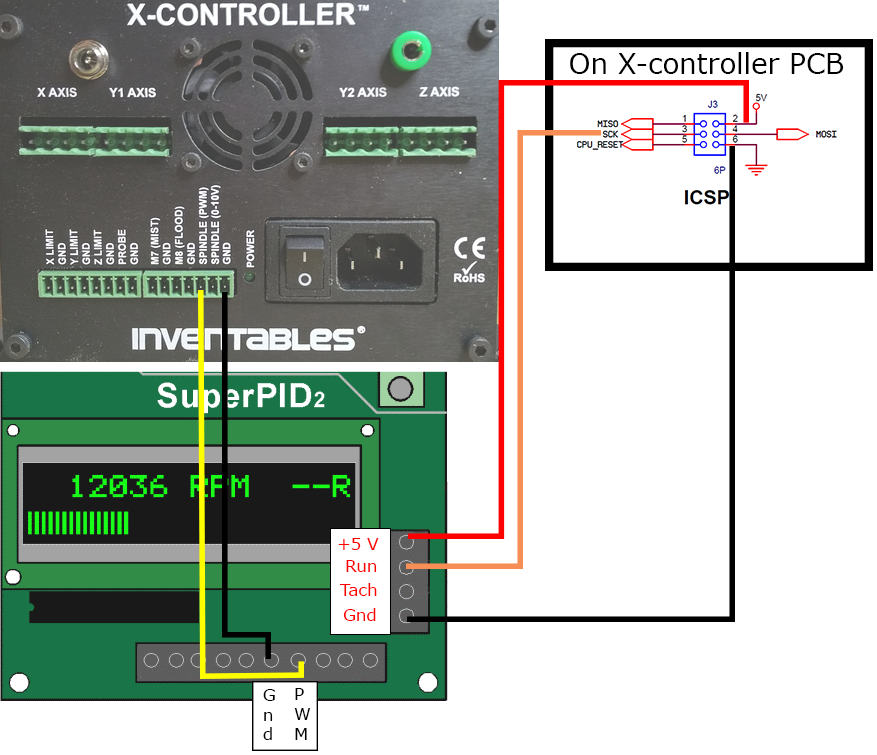
Warning - the bootloader will toggle the SCK pin during a firmware update operation and when power is first applied to the Arduino/X-controller. This will result in a brief spindle on condition during these two operations. Make sure that you have the spindle main power off when using either of these two operations
Here is a basic wiring diagram:
From the SuperPID web site:
• Do I need to modify my router to work with Super-PID?
Yes – Routers with an internal speed control and/or a soft-start feature must be modified to work with Super-PID. This involves removing the router cover and removing/disabling the router internal electronics. We are available for tech support with this router mod. It is a simple and usually reversible modification to your router. Contact us for photo guides of the router mod for your router.
I think we can get away without any mods at all with less than 15-20 USD in parts…
We can use one of this:
Where the ON input pin will be wired to the X-Controller 0-10VDC output.
Then the VOUT output will be wired to the EN pin of :
And then, that relay can control the Spindle VAC mains directly, or you could use any combination of NC/NO of the rely to drive the RUN PIN with a 5VDC voltage source.
This will, with any voltage above 1 volt, turn on the relaying if you use the NO pins of the relay to drive the spindle, it will close and turn on the spindle. When the voltage drops to 0… The circuit will do the opposite in stop the spindle.
This will eliminate any modification to the X-Controller or its firmware. (I Hope)
Diagram sketch will follow shortly…

No, that won’t work.
It is the SuperPID’s job to manage the AC voltage.
Everything you need is provided by the stock X-carve setup with the exception of the “Run” signal for the SuperPID. That’s what you need to generate and then the SuperPID will take care of the router.
The best method for generating the “Run” signal without compromising anything is the method I posted above. Once done, it’s transparent. You don’t have to change any of the software to access full control of the router.
Most, if not all, of the alternative methods involve changes to the G-code sent to the X-carve to accomplish variable speed router control with the SuperPID which means changes in the work flow (may be as simple as a post processor change, etc.)
You can try to derive the “Run” signal from the PWM output (the 0 - 10 volt output is derived from the PWM signal), but there are issues that come into play with that type of solution.
The 0 - 10 volt output has frequency issues which might cause problems if it is used for the “Run” signal and you would lose some of the low end RPM range doing it that way.
I checked the 0-10v line with a scope and it is very stable.
SuperPID is managing all AC load. It just has a switch (relay) between it and the router… When 0-10V is bellow 1 volt the digital switch puts the ON pin to low. Causing the AC relay to open and VAC (High Voltage) to stop flowing from the SuperPID to the Spindle.
The SuperPID still runs from PWM signal.
Am I Missing something that this setup will not work?
The SCK pin might be a better option but require firmware mods… Which I am not against but trying to avoid…, I am just bouncing ideas.
Yes, your diagram doesn’t have the “Run” signal to the SuperPID. Without that input to the SuperPID the G-code cannot turn the router on/off. If you have the “Run” signal to the SuperPID then you don’t need any external circuitry.[quote=“KikoLobo, post:30, topic:12301”]
I checked the 0-10v line with a scope and it is very stable.
[/quote]
You need to look at the ripple on that signal. It’s bad. And if you move to grbl 1.1f it’s even worse because 1.0c uses 8Khz PWM and 1.1f uses 1KHz PWM.
Got it, however in this setup the RUN signal can be always tied to GND. Since the router will not run without the relay being closed.
The digital switch has enough filtering to ease this up to a point where it won’t matter, The input is heavily filtered.
I understand that this might be an overkill. Will see what works best when I get the super PID.
Thank you very much for your input!!
Yes, that would work. Since your switch requires 1 volt to turn on that means you would lose 10 percent of the lower RPM range because you would have to select a high enough RPM setting to get 1 volt out of the 0 - 10 volt terminal to turn on the router.
Be sure to read the warning on the Pololu site concerning the operating model for that switch. It cannot be assumed to work like a mechanical switch. Take the appropriate precautions, considering you are going to tie “run” to ground.
I agree… I think this might be an overkill and maybe it should not be used.
I think that the SCK line is a better option. However just to be clear… once I get the SCK line, I go to the firmware, make the provisions and recompile and reflash the xcontroller correct?
Has anyone contacted the superPID guys to try to find a solution on their end? They could easily make a firmware that could work with the 0-10volt line tight to the RUN to detect when the XController wants to turn on the spindle and when it wants to turn it off. Or even better… ignore the RUN line and when there’s no PWM present, shut the router off.
That it’s a fair concern… I thought that 10% of say at most 20,000 rpm would be 2,000 rpm, my guess is that superPID is limited to 5,000 rpm in the low side anyway. So I will have to experiment and make sure it won’t interfere with use.
The SuperPID interface is common to several pieces of equipment where you have the PWM line to select RPM/power level and a separate line to enable the device. One other example is the K40 lasers from China.
This is the standard model that grbl uses. As mentioned previously grbl has conditional code to accommodate the other model.
I’m not sure, but I think the low end with the DeWalt is about 8000 rpm. So, if you have an 8000 to 16000 rpm range set up in grbl, you would have to request 8800 rpm(( (16000 - 8000) * 0.10 + 8000) via G-code to get the router to turn on and the SuperPID would see the request as 8800 rpm… So you would lose the ability to run at 8000 rpm.
Here are the places that would change in grbl config.h to use the SCK pin technique.
// Inverts the spindle enable pin from low-disabled/high-enabled to low-enabled/high-disabled. Useful
// for some pre-built electronic boards.
// NOTE: If VARIABLE_SPINDLE is enabled(default), this option has no effect as the PWM output and
// spindle enable are combined to one pin. If you need both this option and spindle speed PWM,
// uncomment the config option USE_SPINDLE_DIR_AS_ENABLE_PIN below.
// #define INVERT_SPINDLE_ENABLE_PIN // Default disabled. Uncomment to enable.
// By default on a 328p(Uno), Grbl combines the variable spindle PWM and the enable into one pin to help
// preserve I/O pins. For certain setups, these may need to be separate pins. This configure option uses
// the spindle direction pin(D13) as a separate spindle enable pin along with spindle speed PWM on pin D11.
// NOTE: This configure option only works with VARIABLE_SPINDLE enabled and a 328p processor (Uno).
// NOTE: With no direction pin, the spindle clockwise M4 g-code command will be removed. M3 and M5 still work.
// NOTE: BEWARE! The Arduino bootloader toggles the D13 pin when it powers up. If you flash Grbl with
// a programmer (you can use a spare Arduino as “Arduino as ISP”. Search the web on how to wire this.),
// this D13 LED toggling should go away. We haven’t tested this though. Please report how it goes!
// #define USE_SPINDLE_DIR_AS_ENABLE_PIN // Default disabled. Uncomment to enable.
The SCK pin and the D13 pin are the same and I have tested it for the problem with the bootloader and flashing firmware. The pin does toggle.
So I think this is the best approach,
I wish that GRBL could provisión to setup this with Goode commands or terminal commands to store this setting on EEPROM instead of having to compile it. But no biggie, I rarely update my firmware when everything is running fine.
I still believe that SuperPID could have a setting that can allow us to choose what to conform to. Plus my guess that a good safety feature is that if there is no PWM present, it should meen SHUT OFF. Because even a 0 volt = RUN approach seems counter intuitive for a device that should shut down if its controller goes wild… just me saying anyway,
Sometimes when I am doing research I tend to over complicate the problems that get solved when I get the stuff actually setup .
There is a standard (well, a few standards) definition of the G-code language and this is just not something that the language addresses.
Yes, they could. It’s most likely a marketing issue. Much as we might like to think otherwise, the X-carve is a small part of the market.
It’s just a choice to be made. Some devices use positive logic and some use negative logic. The way to prevent a runaway condition with negative logic is to pull the input high with a resistor and make the controller pull it low to activate. That way if the controller goes bonkers then the spindle is off.
It’s often tempting to go that way. Really, once you get it set up, it’s a one time thing and then you forget about it. You could go years and never change firmware. In fact, I do. There has to be something new that I really think I have to have before I consider upgrading firmware.
1 Like
To use this setup you need to change two settings in the config.h file and recompile grbl.
define INVERT_SPINDLE_ENABLE_PIN
define USE_SPINDLE_DIR_AS_ENABLE_PIN
I’m in the process of compiling grbl with these changes, and noticed another define that looks interesting:
define SPINDLE_ENABLE_OFF_WITH_ZERO_SPEED
Is this something we’d want to do?
Thanks,
-Tom
I compiled and uploaded grbl uncommenting the following:
I also tried uncommenting the following:
I have the x-controller wired to +5v, sck and GND off the board.
The router runs when I start up the x-controller and the superpid boots up. How do I stop this? I have connections to pwm and gnd to spindle pwm and gnd off the back of the x-controller. I also have the pot wired but I tried disconnecting the pot. I have no switches inline to any of these wires.
Do I need to send a gcode command to stop the router? I would hope the controller would power up with the router off.
Thanks,
-Tom