
Don’t know if I’m too late to the party or not but another idea for getting thoes holes drilled if you really wanted to mill the half moon shape out first would be to do so then cut another half moon shape out that fits snuggly into the mounts cut out so the two parts together form the same shape as if you hadn’t cut it out yet. That way you would still be drilling into a flat surface and once all your drilling was done just take the sacrificial half moon piece back out.
Wow that felt long winded so I’m just not gonna spell check it haha


Working on the spindle mount. I need to make a couple of experiments to see if I can machine 3 sides in this fixture.
If tool deflection is not bad, I may mill the mount holes all the way. Otherwise I will mill shallower pilot holes and finish at the drill press.

This is the spindle mount rear piece positioned 3 times after being cut with a square front. Once for milling the front mount pockets and clamp holes, once flipped for milling the mount holes from the other side and once lying flat for milling out the half moon.
1 Like
A drill press will have deflection too, If you drill the mounting from the inside there may be an offset. But if you drill the large holes to leave 5mm and drill the mounting holes from the other side it will be easier to do.
If you bolt two half moons together you will get a full moon circular cut, this prevents the tool entering the material at every pass. That should not be a problem for the B-Carve but the X-Carve may not like that.
By “all the way” earlier I meant to say mill each hole down to its respective depth (as opposed to mill then drill), but it might have sounded all the way to the other side of the block.
So the idea is to attempt to mill the back 24mm deep with a 1/8" bit and the front 26mm deep with a 1/4" bit.
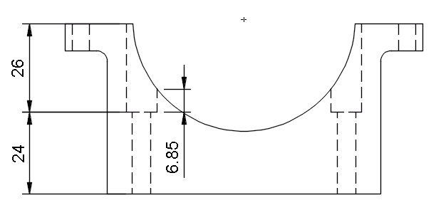
The depth of the final pocket is also shown which -at 6.85mm- is enough to hide a 5mm high M5 DIN912 screw’s head.
I’m not sure I get your second paragraph. I thought to carve out the whole circle from the fixture, so that when I place the part in the fixture (still with a square side) I will have an entry path from the right for 2D adaptive clearing directly at final Z level (no step downs).
So, how are you going to get at the mounting screws when you tram in the head?
Am I missing something?
I forgot the step down, your plan sounds good and should work. We have seen several deep small diameter holes made in aluminium on this forum but I could not find the post back.
I should mention here that all plates and mounts
- will be first milled by the X-Carve as temporary pieces (probably in MDF)
- the temporary pieces will be used to assemble the B-Carve
- then the B-Carve will mill its own plates and mounts in aluminium (probably 6082)
The spindle mount in the setup above might be hard to work in aluminium due to poor chip evacuation. In that case, shallower pilot holes should do the trick. In MDF it should work all the way though and apart from providing the temporary pieces, it will also serve as a proof of concept. Hopefully 
@JanVanderlinden @ErikJanssen For a little while your purple avatars had me thinking that I was talking to the same person and got really confused
Jan, if your concern is the squareness of the XY plane relatively to the Z, I do not shoot for professional tolerances in the X-Carve. I have (as many here) gone through the loosen & adjust all Y end plates method and check as many planes as possible with an engineering square. And then face milled the wasteboard.
If your concern has to do with aligning the two hole pairs, the toolpaths involved all share a common WCS origin. All coordinates for all toolpaths are relative to the fixture. Therefore, it is milled first and stays fixed till the end of the job.
Looks pretty awesome! Where did you pick up the linear bearings and rails?
I got the blocks from here. In order not to risk any surprises with the customs I got the rails from a local shop, which btw has been featured in this forum before when Bart tried out their ATC.
I reside on the other side of the Atlantic, in the birthplace of democracy and unsustainable sovereign debt ![]()


I live at the same side of the pond below sea level. The surprise is 21% import tax and 13,50 administration fee. Together with the shipping cost this is killing for US orders.
Your spindle mount looks very well, concept proven.
When I drilled the mounting holes for the bed and used DIN912 screws, I knew I was blocking half of the slots. The resulting pattern of slots was blocked-free-free-blocked. I therefore designed my wasteboard layout so that the exposed slots would be the free ones.
But the OCD inside me was telling me this doesn’t feel right. What if I want to use multiple configurations on the bed? What’s the point of having a T slot bed and be locked into a single configuration? If I wanted a single configuration I could get T slots between strips of wasteboard. What if I want to get Adam’s kick-■■■ low profile self-centering vise whose mount holes are spaced at 60mm and fit a free-blocked-free-blocked pattern?

The internet is a wonderful place. After estimating all clearances on what I was hoping was a perpendicular shot (by measuring on my screen with a toy plane ruler - don’t tell anyone) I found a countersink bit that could fit the narrow slot profile. Here is the moment of truth.

It worked like a charm. I was able to switch to DIN7991… and to a free-free-free-free pattern ![]()

And then (life is short) I got Adam’s kick-■■■ low profile self-centering vise.

6 Likes
Info on that vise, please!
3 Likes
There is a link in the above post before the pics.
1 Like
Here is a nice one you can build, but not as low profile as the once posted.
http://www.rockrivertools.com/about.htm
jer
3D Carbide also makes one for the Nomad which you could figure out a way to mount. However, CNC-Plus’ is bigger, stronger, has lower profile, runs on 3x bearings & 2x 12mm steel shafts and has 4x M6 mount points. Also, the vise screw itself is M10 vs what-seems-like-M5. In terms of size & strength Adam’s is designed to hold a brick of metal, Edward’s is designed to hold a watch face.
It’s apples to oranges, but it can be an alternative if shipping/customs are substantial and you want to hold accurately something small.
(EDIT: maybe I should ask for a commission ![]() )
)
Two more options of the same concept that can be found in the US:
I have one of those, or at least it looks extremely similar.
The fast-clamping button is bad quality though. I overtightened once, and now it gives way very easily, so I now only use it on the drill press, but not for lateral milling.
fine example of you ‘get what you pay for’.