I’m currently finishing my new cnc build (will share of course!) and I’m kind of confused about microstepping, accelleration, max speed etc. I’ve build a completely new cnc with linear guides and direct screw drive. What will be left of my x carve is the X Controller, the DeWalt Router (for now) and a lot of good memories, fun projects and lessions learned.
Yesterday I activated my x-axis for the first time and it was obvious the settings for the new motors and the direct drive are not optimal (strange sounds etc.). I expected that and read a lot here in the forum, but I’m just not getting it 100%. It can’t be much I’m missing, but I need help, that’s where you come into play 
I bought these stepper motors and I read a few things about reducing microstepping with a direct drive etc.On the X Controller board are dip switches per axis, which can be used to adjust microstepping. As I have read #4 is for holding torque in idle mode, and the first three ones are for microsteps. In the instructions I can read how to set 8x and 2x microstepping. Here are my questions:
- when we talk about reducing microsteps we are actually talking about a higher value, don’t we? 8x < 2x regarding step size
- what about the accelleration, max speed, steps per mm values? I know hot to configure steps per mm properly, but I don’t have a clue regarding accelleration and max speed regarding a direct screw drive. As I’ve read here faster accelleration will mitigate vibrations?
- does anyone have some values where I should be going? 8mm AVMe screw, 2mm pitch
Any help would be much appreciated!
Reducing microsteps would be going to a lower value. Whole steps gives you 200 steps per revolution. Increasing to 2x gives you 400 microsteps per revolution, 8x gives you 1600 microsteps per revolution, etc. You want to go to a smaller value with a leadscrew.
Steps per mm would be your microsteps (say 400 for 2x) divided by your pitch (2mm), so 200steps/mm.
I’d recommend testing for speed and acceleration.
1 Like
A typical stepper motor takes 128 steps to make one revolution. These are known as steps or stopping points. If you turn the motor with your fingers slowly you can feel the “clicks” as it moves from one step to the next. At 128 steps per revolution your resolution or positional accuracy can be improved on by using microstepping. Setting your microstepping to 2 will double the number of stops or steps per revolution of the motor making it 256. So, 4 will increase it to 512 steps per revolution, 8 will make it 1024 and 16 will give you 2048. Depending on your stepper driver you can continue increasing the microstepping value.
Think of it as an old fashioned clock that has a second hand that moves one second at a time then pauses. 1 step out of 60 to make one revolution. Change the clocks microstepping to 2 and it will stop at each second mark and then in 1/2 second it will move half way to the next second mark and so on.
In my experience, setting microstepping to 8 or 16 yields very good accuracy while still providing good speed and power. Just remember, when you change microstepping, you must also change stepper calibration because it takes more steps to travel the same distance when increasing microstepping and visa versa when reducing microstepping.
Acceleration is how long it takes to get you axis up to speed and how quickly it slows down for feed rate change and direction changes. High acceleration values make it increase from “0-60” very quickly and low acceleration let it change speed over a longer distance and avoid sudden starts and stops. Lower acceleration rates make you machine run more smoothly but also increase the time to complete a project. Too high acceleration puts more stress on everything and can make your movements more jerky.
If you axis has a lot of mass then you will want to lower your acceleration to prevent undo stress on your components as well as missing or extra steps. If you have a lighter weight machine, it can handle the quicker starts, stops and direction changes easier.
The machines I build are made from solid aluminum components and no extrusions. This makes them heavier but much more rigid. I have found at a acceleration value of 7-12 for the Y axis works and a little higher on the X axis.
If you find that your whole table is shaking from side to side while running at high feed rates then you should consider reducing your acceleration. Nothing good can come from a table that is shaking. But smooth starts, stops and direction changes will definitely improve your cut results. The key is to stay inside the limits of your machines capabilities and you will be successful. That applies to an X Carve as well as my machines and any other CNC machine no matter the cost or rigidity.
Hope this gives you some insight.
Charley Thomas
Triquetra CNC
4 Likes
Hey Charley,
I deal with a lot of steppers and I’ve never seen one that does 128 steps.
1 Like
The linked motors are 1.8deg => 200steps/rev. Microstepping is a trade-off between torque and resolution, i.e. high microstepping provides higher resolution and lower torque. And vice-versa.
For instance, if your leadscrew advances 8mm per revolution then:
1/1 ustepping => 200steps/rev => (8mm/rev)/(200step/rev)=0.04mm/step
1/2 ustepping => 400steps/rev => (8mm/rev)/(400step/rev)=0.02mm/step
1/4 ustepping => 800steps/rev => (8mm/rev)/(800step/rev)=0.01mm/step
1/8 ustepping => 1600steps/rev => (8mm/rev)/(1600step/rev)=0.005mm/step
1/16 ustepping => 3200steps/rev => (8mm/rev)/(3200step/rev)=0.0025mm/step
I’d say pick 1/2 or 1/4 if you’re after detailed work and believe your machine is sturdy, accurate, low-backlash enough.
Then speed and acceleration are pretty straight forward. For each axis, start with low speed, low acceleration and increase speed gradually till you stall your motor. Then back off (10% is okay). Do the same for acceleration.
3 Likes
Thanks guys, I really appreciate your help and I think I now understand a lot better what to do and will try new settings next weekend! Ihave a 1.8° aka 200 steps motor which seems to be the “standard” here, at least I’ve found many like them.
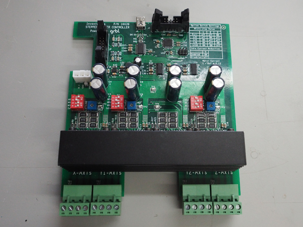
Thanks for the examples! Can you tell me about the dip switches on the board? In the instructions I’ve just found 2x and 8x and I don’t get the System underlying it 
All microstepping dip switch combinations (from 1/1 down to 1/16) are found on the PCB itself. Look at the upper right corner.
1 Like
Oh wow. Thanks. Now I just need to figure out of I’m dumb or blind 
You are absolutely correct. I think I combined 1.8 degrees per step with 200 steps and came up with 128. Even that doesn’t make much sense so rather than try to justify it, I will just concede. Thank you for pointing that out. Better to have egg on my face than to pass on bad info to others that don’t know. I believe the rest of my explanation was correct aside from the numbers relating to steps.
Charley
1 Like
Your explanations were excellent! I was just questioning what steppers you were using. I wondered if you had some sort of analog servo motors running.
1 Like
Digress alert 
Another difference in “full step” vs “partial steps” is that precision is best at full step position (5% or so accuracy ) but partial step position may be 20% or more off.
Microstepping primary function is to smooth motion. So use as little microstep as possible.
3 Likes
