
Does the 1/8" Elaire collet have the range to clamp a 3mm tool?
Hope so, if not I will use it with the 1/8" v-bits I use and ask for a custom 3mm collet. I would order one at the time anyways in order to avoid import tax duty/handling fees
Inspirational link below ![]()
My gantry is weak with only 19mm MDF as main structure and especially the X-axis would give me a bit of chatter (and broken bits) when doing aluminium.
The back side of the backplate holding the SBR16 rails (X) is mounted 20mm in relative to the side plates.
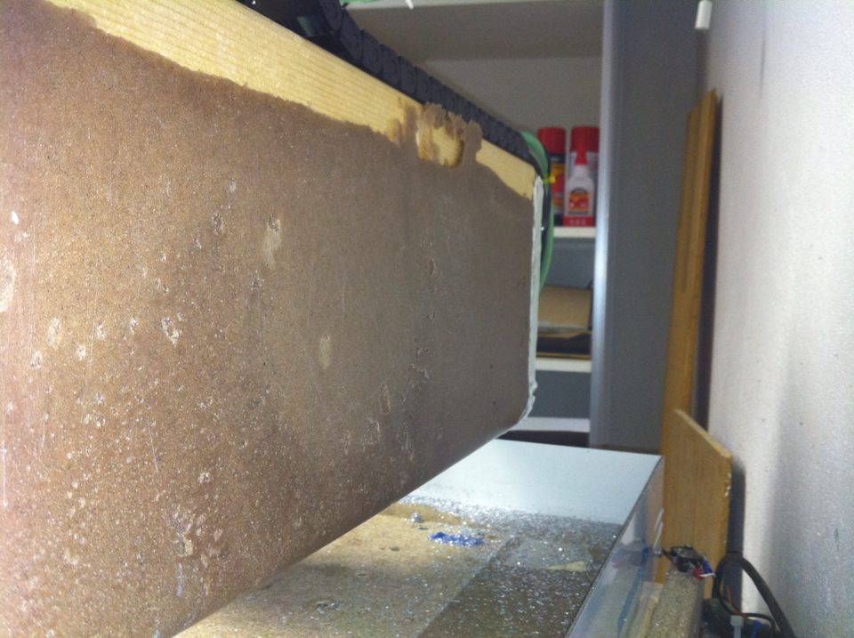
Calculated the volume of this “pocket” and estimated the mass =>
2800g of sand and 700g of epoxy.
Made a quick casting form closing the backside and tixed up a batch of epoxy granite.
The CNC is now running again and close to finish a 2hr session with no issues. The added 3500g (about 7lbs) of mass really helped. Next step will be to use EG on the side plates swell and this whole excersise will will eventually lead to a new CNC where EG will be the main material ![]()
Picture show before/after, red solid = EG.


1 Like
This dude has done some very interesting (and very advanced) projects .
Did you use his recipe #7 ? How did you attach it to the back of the gantry? Did it just stick to it while curing?
Indeed he has!
Yes, sand only and 20% epoxy (by weight). For higher rigidity greater variation of grit size will be required.
The EG will bond quite nicely to MDF alone I am sure but I have the bolts holding the two SBR16 rails (X axis) protruding almost 20mm out the back.
So these secure it to the back plate. In order to keep these screws removable I treaded them with washer (W) and nut (N) so they have a WNWNWN “sandwich” that is locked into the EG matrix.
New 3mm 1F’s have arrived, 6mm flute length and looking forward to put them to use. Hopefully the Elaire collet arrives soon…
Also tried 2mm 1F cutting thin aluminium sheet (1mm) which worked very well.
22k RPM
400mm/min
Full depth pass
Mister (air & denatured alcohol)
Now we are talking…
New fresh 3mm 1F tested:
Tool stickout 10mm
550mm/min @ 22k RPM
Chip thickness 0.025mm
Depth per cut 1mm
Stepover 2mm
(+ tested chamfer in F360 for the first time)
Went like a charm… 
Pocket is 10x20mm and 4mm deep. Chamfer 1x1mm:


1 Like
Short video:
Today I made a 2hr continuous carve with the same settings as last nite, this is just the initial minute or so.
Makita at speed #4 and after the carve nothing was feeling hot (the Makita base/bearing/collet barely warm to the touch)
Before the added mass to the gantry using sand/epoxy I could only do 0.2mm DoC in aluminium with the same strategy as shown here.
1 Like
Well done!
What’s astonishing is the difference in surface finish on the pocket’s vertical wall vs the out of focus front wall (which looks like a tidal coast  )
)
~1cm^3/min MRR and 0.025mm chip thickness is this tool’s sweet spot. If you have not done so already, I’d suggest to create a spreadsheet with all cutting parameters per tool and material. I keep a record with the following columns:
material, bit dia, flutes, model, stickout, operation, DoC(abs), DoC(%), WoC(abs), WoC(%), chipload, chip thickness, surface speed, speed, feed, MRR, deflection, kW(abs), kW(%), comments
1 Like
Thank you, the added mass/stiffnes really transformed the results for me.
The surface “finish” seen on the outside of stock in the previous image is the result of 2D Adaptive roughing pass (trochoidal). So the difference isn’t that big 
But previously I couldn´t get near the MRR I managed today with 2D Pocket
I have a spreadsheet that I use but it isn’t really comprehensive…!
Mind you @EliasPolitis, you have been very helpful with sharing good points to learn from and I really appreciate that. So thank you very much for that.
Haven’t really had much time to play with my CNC so it has taken a while to reach the point where I am at right now. But that allow things to sink in 
Thanks for sharing too. I’m in a process of constant learning as well. Exchanging ideas, successes and failures can be bidirectionally beneficial 
Out of this thread I’ve already bookmarked the Sorotec Proalu range and taken homework for epoxy granite.
Indeed, that is why I posted my failures as well
EG is a very appealing material to work with, I have some casting experience from my RC aircraft days and its characteristics with mass damping is apparent with my modification. Costwise it would be similar to all alu build, downside is weight (fram a handling point of view).
I would like to utilise flood cooling when doing metals, my current wooden frame would not take that well. EG can take pretty much anything relevant to CNC-ing
I have plans for EG-Carve
(Model mainly made to get volume => weight calculations)
Currently limited to 400mm in Y-axis but have 750mm SBR16 rails, the EG-Carve will take advantage of that and I hope for 400x600mm travel in X/Y. Design will be made adaptable to Hiwin at a later stage.

Prior to Christmas I started sourcing parts for the new build. Starting small.
My current Z-slider which is built crudely by myself need some improvement, both in travel but also rigidity and precision as the L-bracket holding the motor flex due to the ACME/coupler not being totally in-line.
Current Z range is 70mm, I should get 125mm of this new design.
Now that I seem to have gotten the CNC to work nice with aluminium ut ´it is time for it to rebuild itself
So I am starting with a new Z. I could probably buy one and save me the hassle but the DIY-er in me said nope… 
MGN12 rail/blocks for Z-lift, 1605 Linear ball screw and Nema 23, 270oz.
The MGN12´s have arrived and seem quite firm, hope they hold up.
The 1605 is also on hand, did actually order the 1204 but got this instead. Minor change but no big issue. Perhaps I should have opted for 1610 instead to gain better microprecision since speed is not a priority with Z-lift.
Current Fusion360 render, while preparing the files for milling. Hope to source the metal tomorrow

1 Like
Can you post a bottom view?

In the first snapshot the (blue) rail riser blocks looked about the same width as the rails (~12mm) which would be rather slim relative to their height. From the bottom view though they look like ~20mm thick which should be sufficient.
Btw, if you (have the time and) want to be extra precise, take a last facing pass on the top of the riser blocks after they are mounted on the back plate.
The riser blocks are indeed intended to be12mm though I have thought about narrowing the fixed Z-plate a little so the edge sit flush with the risers. That way I can bolt on a 2nd 12mm side plate.
The risers will sit flush against the Bk/BF blocks which will offer some support so I think it will be rigid enough. But if not I have other options to utilize.
Good tip with facing the risers after installation, the mounting plates themselves will also be faced.
Hm… if you use this ballnut mount

and try to bring the riser blocks closer together, then the rails blocks will touch the ballnut mount before the (12mm thick) riser blocks touch the BF12, leaving a 3.5mm gap between each riser block and the BF12.
In case you use 20mm thick riser blocks, you can sandwich the BF12 between them and still have 0.5mm of clearance between the rails blocks and ballnut mount.