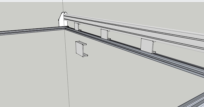
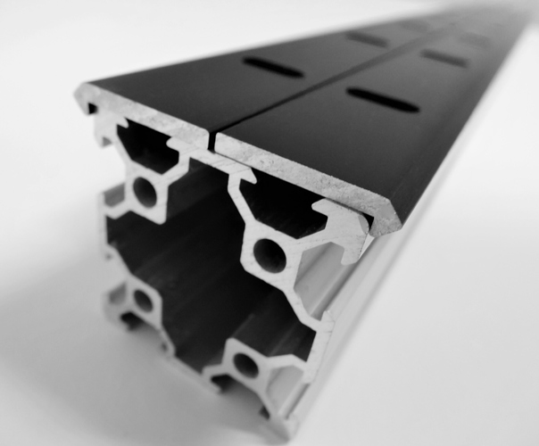
I mentioned this in another thread, but I was thinking of getting some 20x80 extrusion and drilling holes in the face to allow for bolting to slot nuts in the Y axis maker slide. This should add a lot of stiffness both for drop as well as torque. If there’s clearance you could bolt it so the 20x80 extrusion extends above the level of the maker slide to help block dust and chips from getting in the track. I was also thinking if done right it could allow for butting extra maker slides up to extend the Y axis beyond the 1800mm currently available. It might take quite a bit of work to get the joint of the maker slides aligned to prevent impact to the quality of the work, but it seems like it might work.
You can solve this with Lab Metal to seal and sand the gap. The stuff is amazing and brushes on like paint, just make sure to get the solvent along with it for cleanup, thinning and to put on top for storage.
One thing to remember is to get you rail as close to straight as possible. This is not as easy as it sounds. There are no good reference points that you can verify as straight. One way that takes some time and engineering is to use tight wires.
With the belts off and the top holes in the Y end plates clear get some .010" music wire. Mcmaster-Carr sells it.
You stretch a wire from one plate to the next and make it harp string tight. This wire is now for our needs straight. There are engineering references that will give you the amount of sag due to gravity but it is so small we do not need to worry about it.
Now you have a known reference. using good measuring equipment you can check the distance from the wire to the rail at both end and make sure they are the same. then you can start measuring along the wire to the rail and adjust your mid span supports to get the rails just as straight to your reference wire as you can.
Do this for both sides.
You can also use this to make sure you don’t have any bow in the rails that they are the same distance apart on both ends and in the middle.
If you really want to get serious about this you isolate the wires from the frame so you can use an ohm meter and a micrometer adjusted device that sits on the rail and as you raise a finger on it with the mic when it touches the wire and completes a circuit you see a reading on you ohm meter. Check the reading on the mic and move to the next test point. Repeat, is the reading on the mic the same or different. Is it high or low. Adjust as needed and retest.
This could give you a rail that is straight to a couple of thou.
The big thing here is if you want your machine as accurate as possible you have to have good reference points.
Hope this helps
Dave
A good quality 4 foot construction level is a pretty good reference. The edges are ground, so they should be flat and accurate to a few thousands, if not better.
Careful using it as a level though. A good quality level is only accurate to around 0.0005" per inch at best. That’s about 0.024" of 4 feet. Good enough for construction, but not a CNC machine.
I own a machinist level that is accurate to .0005" in 10" that I would never use on my machine because just walking around on my shop floor changes it.
The difficulty with levels is getting a good reference point to start from and as Sun says construction levels are just not up the the job.
Getting these machines square, parallel, flat, straight, etc is all about reference points.
Dave
I think @SungeunJeon was talking about using the ground straight edge of the level and not the bubble itself… it would provide a straightness reference point for measuring from.
The difficulty I have with using a straight edge is what do you use for reference points for that straight edge. Also how do you use a straight edge to check that the 2 Y rails are parallel to each other.
Dave
How about a piece of C channel aluminium? You’d need to move the lower rail out so it is directly under the MS. Getting C channel with the right dimensions might be a problem but the brackets could be machined from a solid block
The only problem with that is the lower rail has 2 attachment points for the wasteboard, and on the left side the drag chain attachment is in the way. You could buy 2 extra rail pieces and attach them, but you’d have to cut some notches for the drag chain rail.
You’d only have 1/4" to attach it also, since the v-wheels and screws protrude over the slot.
As I see it you have to work from your table you are mounting the machine to up. The base rails need to be as straight as possible. If the rails bow up and you set the Maker slide rails to equal distance from the base rails then the MS rails will have the same bow.
If you build your machine table as a torsion box construction and insure that it is dead flat in both X and Y plus the diagonals and then attach the base rails to this table you then have a good reference point for the rest of the build.
Again using tight wires to measure to helps.
Dave
At the risk of being a dumb question, does it make a difference where you drill the holes through the Makerslide for the X-axis mod? Line A or line B on the attached diagram.
I figure Line A would mean more holes but I could use smaller bolts that wouldn’t protrude out far enough to affect x carriage movement plus the stepper wire could still be run through the centre of the MS.
Please let me know if I’m over thinking this, I’ve been breathing MDF dust all day. 
Brilliant! I’ll be implementing that soon. Thanks for the share.
I chose B since the bolt and nut heads were large, so they would be fully engaged with the aluminum instead of only contacting on either side of the slot.
Going through both A marks would be good if the bolts don’t interfere with anything, and if you can figure out how to get a decent sized bolt and nut buried in the slot. I torqued the heck out of mine, and would have damaged anything that used the standard M5 slot nuts.
Could go either way. If you want ultimate stiffness, A may be the way to go. I think that may be beyond the point of diminishing returns though, since you’d spend more time and do more work to stiffen up something far beyond the accuracy the of the rest of the machine.
I think for stiffness staggering from the top A to the bottom A would be best.
To deal with interference you could use a flat head machine screw, counter sink the heads and if you want to get crazy, tap the backside. This way you would really have anything sticking out!
My plan is to put 6mm dowel pins in position A and 5mm socket head cap screws at position B.
This will have to be done in a milling machine to keep the alignment correct.
This should give me the best of both worlds.
Dave
Hi David,
I did something a little bit similar. I used M6 button head screws and pre-installed them into predrilled and tapped holes a 3/16 piece of aluminum so that they will rest at position A on both sides. I had already determined that the button heads would fit into the inner t-slots with just enough play to loosed an tightened. I then slid the whole assembly. into the x-axis after removing one y-axis plate. I very carefully marked and drilled holes in the maker slide to access the m6 screws with a hex wrench. I’d seen the “drill access hole” technique used by people building with 80/20 extrusions, so I thought it would work. It does work, but I’m not sure it was worth the trouble relative to the method everyone else is using.
Wow, maybe a little complex but still very cool! That’ll definitely stiffen it up. 
Why did you decide the aluminum T-bar wouldn’t work? I think it’s a great idea, but saw that you decided against it.
Anyone use OpenRail from open builds?
They are bolt on v rail, you could get a 40x40 extrusion pop these on and connect to the gantry plate. And if I am correct in my measuring, you mount them in the oposite direction as in the picture and the spacing is the same as the current two makerslides with the 3/16" space. The only modification would be to widen the holes in the gantry plates so it fits the 40x40 extrusion.
I’m not sure it would be any better than 2 makerslides and the steel/aluminium bar between them. The centre of the extrusion has no support at all.


