And here’s a rendering.

7 Likes
Following SE3 
Thorough explanation as always and I concur.
When considering a performance and repeatability upgrade a servo-based system is not that much more. And for a system that generate income its a no-brainer.
I have the Clearpath on my wish list but it wont be viable untill my whole CNC is rebuilt using better materials.
She’s a beauty Elias. Following as always… What sort of extrusion are you using for your x and y?
This is all 30 system (30mm base size, 8mm slot). I had enough T nuts and brackets already and could reuse the existing extrusions, with very few additions.
X gantry: 60x120
X crossbeam: 30x90
Y walls: 30x90
base: mix of 30x30, 30x60, 30x90
bed: 15x120
UDAPTE:
I’ve found that this combo works really nice together:
30 system, slot 8, 15mm rails, NEMA23, <=2kW spindle
One level heavier I would pick:
40~45 system, slot 10, 20~25mm rails, NEMA34, >2kW spindle
1 Like
dude I always look with awe to whatever you come up with. Expect a lot of questions from me whenever I decide to design my own cnc.
I agree here. On my self build CNC at 1000x1500 I used OpenBuilds C-Beam for most of it and If I ever decide to take it to a full 48"x96", I’ll plan to use 40-45 and reuse the rack/pinions.
Great job with the design and implementation/upgrades.
Jer
@anon68752607 thanx, I’m following your laser build too.
So, here we go. I cut a couple every night for about a week.
Foot plates, gantry plate with ballnut location moved to top, side and L plates for joining X to Y, taller Z plate, spindle plate for four blocks, front & back Y bearing plates, and a little crossbeam plate. Out of 10mm 6082-T651

5 Likes
Wow!! A beast!!
Nice work!!
Top part of base.
(Too much detail #1: The four short 3060s are not that important structurally. It has to do with settling on the final base width, taking into account the width of the bed pieces. Previously I was using 6 pieces, 120mm each, 720mm total. Given that the Y sides are now above the bed surface, keeping 6 bed pieces would bring the total width to 780mm. For the rigidity reasons discussed earlier I did not want to go over the original width. On the other hand 600mm wall-to-wall would mean losing 120mm of X travel, which I did not want either. So I settled in the middle, 660mm, 5 bed pieces and these short 3060s to fill the gaps. They can also serve for work holding by using post-installation nuts.)
Btw, there are hidden corner connectors that hold the the 3090s together.

I was too lazy to draw these in the model above: rubber feed with M8 threading for leveling and to help with absorbing vibrations too. Nut and washer for tightening.

Base assembled. The Y rails are still loose and so are the Y bearing plates.

At this stage I wanted to confirm screw lengths and quantities. I ran out of DIN912 ones (deeper socket, bigger size allen key => can take more torque) and had to use some temporary ISO7380 ones.
(Too much detail #2: The temporary ones were used on horizontal slots, so they could be easily switched out. Had they been used on vertical slots, that would have resulted in dropped nuts, fishing, face palms and lots and lots of cursing at switching time).
One thing I love about CNC (from building, to cad, cam and workholding) is that it’s like chess. It constantly makes you think several moves ahead.
6 Likes
Did you choose trochoidal cutting (2D Adaptive) or 2D Contour with a stepover pass?
I have found the latter to give high quality finish (within my CNC capability) and work consistency. Running deep single path slot can give me issues aka chatter/performance/quality issues.
My weak link is stiffness on X as I can by hand push the bit 0.5mm before the whole machine slide on the desk ![]() I would be very curious to what deflection your v2 would see with say a 5kg side force in X/Y.
I would be very curious to what deflection your v2 would see with say a 5kg side force in X/Y.
All roughing is 2D adaptive at full DoC with a tiny “radial stock to leave” value. Then a 2D contour finish pass takes care of that.
With the new electronics I will be able to achieve even higher chiploads at deep cuts (both good for tool life).
I also tried something new this time to save on cutting time on far-from-rectangular pieces (e.g. the big hypotenuse of the side plates). Previously I’d make a quick sketch, project the part, create an offset and cut trochoidal slots inside this channel. This time I got a multipurpose blade (54 teeth, negative rake) for my small circular saw (no space for table saw), print out a drawing of the part, stick it on the stock, then cut off the big chunks. Then I used the same offset sketch, but this time as “stock contour” in Fusion. A lot faster toolpath, as the former spends half the time repositioning.
UPDATE:
Here’s a visual of the above comparison.

Fox in socks on box on Knox. (gantry plate on blocks on rails on gantry extrusion)

L plates on Y blocks.

Gantry on L plates.

Side plates, gantry and L plates bolted together.

There’s a shallow groove machined on each side plate, not just to help mate with the L plate, but to assure squaring/alignment.
4 Likes
Looking top-notch, as always ![]() With the servos it will scoot around faaaast!
With the servos it will scoot around faaaast!
I did the same on my Z lift plate, where the Makita mount to. The holes for the blocks was done at the same time as a -1mm face for the Makita bracket was done.
, this to ensure it would mount perpendicular to the bolt pattern.
I didn’t think to take a picture of the X and Y calibration, so here’s a drawing instead.
X is straight forward. One rail is fixed parallel to the extrusion, the other is loose. The dial indicator magnetic base sticks on a rail block and the indicator travels on the precision ground face (the one marked with an arrow) of the other rail.

Y requires more creativity. Again, one rail is fixed parallel to its extrusion, the other is loose. Both rail blocks are fitted on the fixed side with the L plate on top. I then used one of the old gantry 3060 extrusions as an extension. A 1-2-3 block is bolted close to the edge to give something for the indicator base to stick to. The indicator is slowly moved by holding the L plate only. Nothing else gets touched.

3 Likes
Y ballnut mout on crossbeam plate. Squared and tightened.

Crossbeam plate on crossbeam. Loose.

Crossbeam fixed between side plates. Y bearing plates fitted loose.
Looking from the front (XZ plane) there is +/-1mm adjustment range on Z and plenty on X (the whole extrusion slot). The order that provided the best alignment was: move gantry to the +Y end, fix crossbeam plate, move gantry back midway, move to +Y end again, fix +Y bearing plate, move to -Y end, fix -Y bearing plate.

Looking from the side (YZ plane) there is +/-1mm adjustment range on the Z and +/-0.5mm on the Y. Similar order for alignment: gantry to -X end, fix ballnut mount on gantry plate, retreat midway, back to -X, fix -X bearing, move to +X, fix +X bearing.

Bed in place.

All moves at this stage were done with a cordless drill. Otherwise at 5mm/rev it would take forever by hand. The cordless drill also helped verifying that everything runs smooth. This was done at its high speed (1500RPM or the equivalent of 7500mm/min).
3 Likes
Good to see that the high mounted X ballscrew is performing well, high above the chips it will stay clean too.
How is your table doing, it all looks pretty heavy.
Haha no they won’t ![]()
For instance a 6mm 1F bit running with 17-24k RPM will create a 2m radius fall zone ![]() Ask how I know
Ask how I know ![]()
How do you know? 
3 Likes
It’s heavier than the original build, but I wouldn’t mind if it was even heavier. This question strikes a chord. I think I still haven’t decided if I want a cnc router or a cnc mill. So, I’ve ended up with something in between.
Indeed, some cuts just wanna fly everywhere. At some point I’ll reveal my ultimate mess containment system ![]()
…aaaand here’s the Z.

Nothing new here. Just a bit taller than the previous for a second pair of blocks to fit without losing any Z travel. Build process same as in post #195.
1 Like
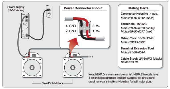
Made some cables. The connectors are:
8-pin Mini-Fit Jr (signal, motor side)
4-pin Mini-Fit Jr (DC, motor side)
2-pin Sabre (DC, power supply side)
8-pin Mini-Fit Jr (AC, power supply side)

The power supply has two DC ports. One will go to the Y motor which will be doing the heavy work, one will go to the X & Z in daisy chain. This works well with cable management too. Here’s the relevant excerpt from the manual.