How did I miss this entire post!? Damn @PhilJohnson. I may have to quit my job so I can pay more attention to what your up too.
Awesome stuff
No I haven’t seen the motors or belts. I’ll look for them. I’m impressed with your web site set up. I had to buy the gear clock lol.
Wow! What a fantastic thread. Phil, thanks for pushing all of this incredible info to the community. I am still in the research phase of my build so have a million questions, but ill try to keep it short.
It seems where folks get their drivers and motors has a lot to do with how happy they are with they build. Any suggestions for good (cheap) suppliers of drivers, motors and PS? Also, i might have missed this, but why did you decide on a 6600 based driver?
Also, im thinking of a proof of concept project to get familiar with all the wiring needed for this. Any suggestions? I already have experience with arduinos, software etc. and i am a wood worker / DIY nerd. It is really just the electrical part of all this that i need some experience with before i dive in.
Awesome! Thanks, yes, would love to buy from SO, but their shipping is almost more than the hardware! I search around a bit more.
As for the POC, i just bought a cheap Nema from Amazon to test out the full architecture.
Why did you use the barrier strips and all the wires rather than soldering up a perfboard? Basically make your own shield? Maybe not for power, but at least signal.
Tip- DON"T wire your grounds to DC ground (AMHIK) 

Sure is! Just need to fix some issue with the unit cutting lines when surfacing the waste board. They cut along the x axis but not the y and you can hook your fingernail on them when dragging from back to front but not front to back which leads me to believe the Z is not perfectly vertical.
You mean signal grounds, ya?
Also, unrelated question: is the wiring diagram in post 67 for grbl 1.1? Whats up with pin 11? other than understanding what PWM means, i don’t get the grbl wiki at all on this topic. #nube
There was a pin change between grbl version 0.8? and version 0.9?
In version 0.9 the Z axis homing switch was moved to pin D12 to free up D11.
D11 is a pin that can do PWM (Pulse Width Modulation). PWM can be used to control the rotational speed of spindles that can accept PWM signals.
Some people use a special case of PWM to control an on/off relay for turning a router on/off that does not accept PWM signals.
Since D12 cannot be used for PWM it was logical to move the Z axis homing switch to D12 to free up D11.
The pin swap carried through version 1.0c and 1.1f
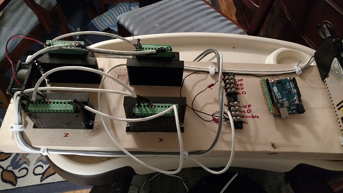
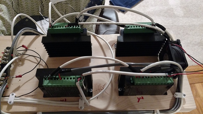
Ok trying to tackle this controller and I thought I had it until recent posts. Few things I want to check to make sure what I am doing is acceptable.
What I have so far
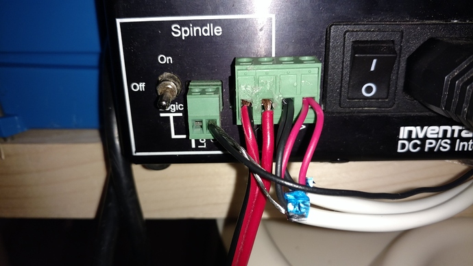
Seeing the grounding post got me concerned, I am running ground and power from the original DC interface. V+ and V- going to the VCC and GND on the drivers. The shielding ground wire, pul-,dir- and ena- going to ground on the spindle section of the interface.
When I was wiring I went from V+/- to the first steppers VCC and Ground, then I used another wire to go from that stepper to the next steppers VCC and Ground. I used that same strategy for the Ena+
Slightly closer look
Anything I should be concerned about. At this point, I guess this is a check my work.
Thanks everyone!
Any problems with daisy chaining the power cables? Aka do I need to order some more barrier strips? I will switch the ground to the Arduino instead of the DC interface.
Daisy chaining the power cables between the drivers are usually not recommended. You could add a capacitor for each at the input terminals to act as a buffer. 1000uF 50V for instance.
ok, two more questions quick questions.
- Why do you bridge the PS grd and Ard grd at TB4-1 and 2? As just mntioned, shouldn’t the signals go to Ard and power go to PS grd?
- What are the terminals marked “To x MTR SHLD” on TB5-1 - 4?
Im sure the above questions are obvious, so apologies as i probably missed something.
Thanks again for all your work on this!
AH! I wondered where those drain wires went. Awesome. So no drain wire from box to motor / switch but yes once inside the box? Any reason? Any harm in having all motor and switch cabling have drain wires?
Ok, ill cool it with questions after this. I promise.
Even if it is not connected to the motor / switch?
Not only does it lose its effectiveness. It will create a ground loop. That will intensify the EMI. = the craziest stuff you’ll ever see your machine do.
Yes. The only wires that should go to DC ground V- are the negative power wires for the steppers. The arduino, homing switches, pwm signal, touch plate and drain wires on the shielded cable should all go to earth ground. (I may have missed something. Someone else will remind me if I did.)
Just a quick heads up regarding the SBR rails:
Take the screws that join the guide with the mounting bracket out and reinsert them after applying blue Loctite to them. I have SBR’s on mine and some time ago I noticed slack somewhere. Couldnt figure out where untill I noticed the rail bolt on one end had come loose.
Good proactive measure to perform before bolting it all up ![]()
For the DIY’ers out there, this video is very simple/good related to Phil’s original theme for this thread:


