The Whittler's Upgraded Whittler (XCarve 1000x1000)

Here are a couple of pictures of my recently built XCarve. I had intended to take pictures as I built it along the way, but I didn’t seem to find the time and just got on with building it.


It has a wasteboard/base inspired by @PhilJohnson 's using the same 20x20 frame underneath, but I went with a 10mm Aluminium plate.
I carried out the 60 minute X axis upgrade, and also added some 4x2 Aluminium angle along the Y rails. This has seriously beefed up the frame.
I also used the alternative method for the eccentric nuts by @Mike as I really don’t want them coming loose, and used socket head cap screws for the pulleys as I’m not really a fan of set screws. The hardware was also replaced with stainless fasteners as rusty bolt heads would have bugged me (seems quite common with the black finish).

I ordered my Xcarve along with the Dewalt 26200 Trim Router (that was the only option from the UK supplier), but after reading a lot on the forums I was worried about the high minimum RPM’s. This led me to look for an alternative, and after much searching I settled on the Kress 1050 FME-1 to get me started. I like the fact that it had a 5-25k RPM range, and they also have a good runout guarentee.
I had a bit of a dilemma after ordering the Kress and seeing people using the universal spindle mount plate, as they had trouble getting the cutter low enough. I ended up using the specs for the universal spindle plate and made up a drawing to suit the mount I had bought for the Kress.
I have the Kress controlled with a Solid State Relay, which the arduino turns on and off with the CNC program.

I fitted the XCarve with Creltek Hall Effect Limit switches from Kevin Patterson. I had intended to make some up, but I could have never matched the quality/finish of his parts

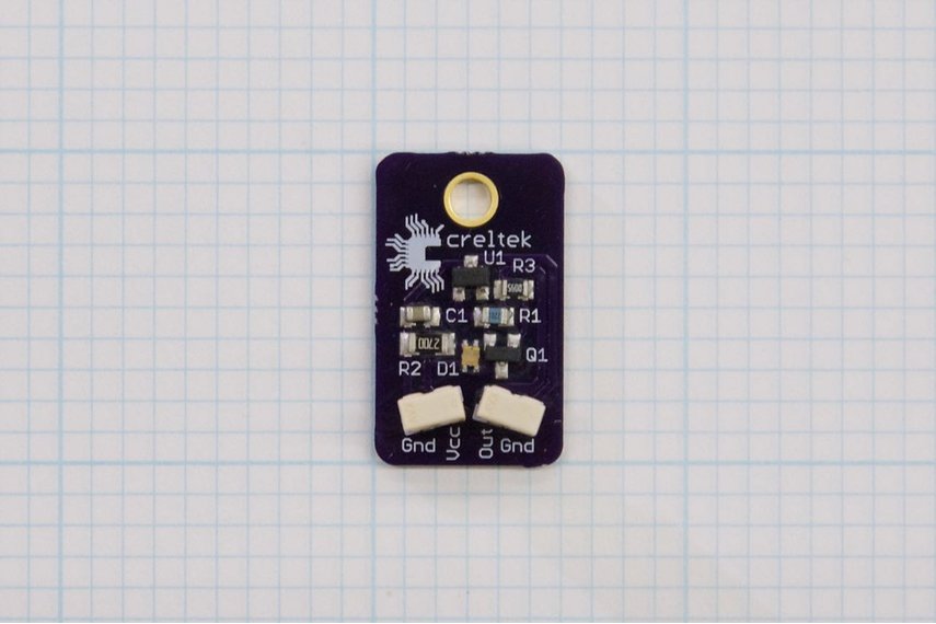
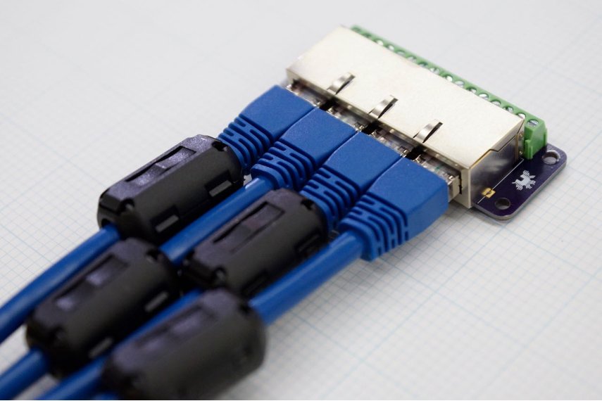
While looking at his store I noticed the other CNC related parts he had and also ordered his Stepper Motor, and Limit Sensor breakout boards. Again the parts were of a lovely quality and due to the built in shielding/grounds I have had no issues with interference. They also use RJ45 and RJ11 cables respectively which keeps things tidy.

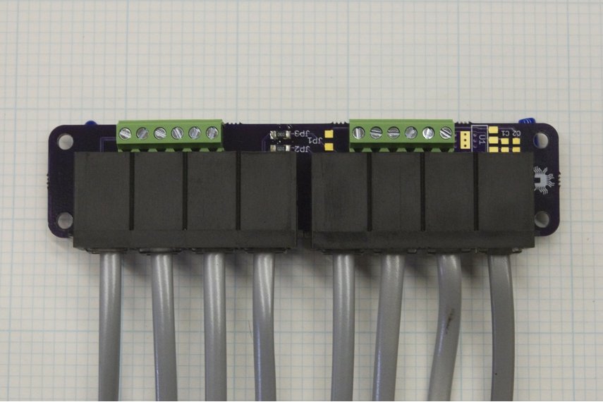
Here is a picture of both boards


Everything was received well packaged and quickly despite the US to UK postage, and Kevin has been very helpful and answered any questions I had. I am in no way associated with him, and am just posting these links/pictures as someone else may benefit from his great products.

After seeing mention of it on the forums (and then doing a lot of video watching/reading) I decided to go with Estlcam for both my CAM, and also as my machine controller. I have been very happy with it so far, and the program works wonderfully.
The main factor for initially going with Estlcam was its completely offline functionality as I do not have a good internet connection in my workshop, but after looking at the creators youtube account all of the extra things the program does sealed the deal and I bought a license.

I think that is everything covered, but I imagine I have forgotten something.

10 Likes

Nice build Whittler! Seeing all these builds is making my even more anxious to have my machine up and running!

Of course all these fancy upgrades like the hall effect limit sensors and stepper breakout board you guys post usually result in me buying them so my bank account is slowly circling the drain but that’s a problem for another day :sweat_smile:

His note about using CAT6 for stepper motors is a bit disingenuous.

"Each jack provides 4 motor drive signals on specially selected differential pairs within the cable. This allows twice the drive current compared to conventional stepper wiring… "

True only if your “conventional stepper wiring” is 23AWG wire, which no one would do. The rated maximum for two of those wires in parallel is about 200mA, so hopefully you’re using less than that per phase on your steppers. That is, something smaller than a NEMA14. Though it looks like you have NEMA23s.

I had the cables made up locally (as Kevin Patterson only supplies 7ft lengths), and they stated they could handle 4A used in pairs on 24V. I have no idea what gauge the wire is, I just told them my requirements and they gave me a few options. I chose the highest rating they could give me while still using the RJ45 connector

I think the real problem may be resistance in the connector contacts. There isn’t a lot of metal to metal contact there and if one were to run the steppers hard things could begin to heat up

To be honest I hadn’t considered that, but I guess I will just have to keep an eye on things.

Today I ran a couple of fairly long carves (5 hours ish each) with a lot of movement, and kept an eye on motors/wires/electronics as the machine is new and hasn’t worked for that long before. Only the Z motor was warm to the touch and everything else seemed normal, but I will definitely keep a close eye on temps

I took a look into the question regarding CAT6 cable carrying the required amperage for the Nema23s and it looks like using even CAT5 is something people have done surprisingly often. The general consensus seems to be that a sustained 3A+ load would eventually fry the wires, especially for a long run cable, but for short runs (2-3m) these loads should be fine especially since the steppers are being driven by a pulsed signal and the average load should be lower than the peak current per phase of the steppers. The question seems to be more often whether or not the RJ45 connectors themselves can handle the load but again it looks like as long as you’re not pumping a constant 3A+ through the connectors you should be fine.

CAT6 generally seems to have 23awg wires so a twisted pair gives you ~ a 17awg equivalent and based on the chart towards the bottom of this article that should handle at least 2.9A.

http://cablesondemandblog.com/wordpress1/2014/01/30/cables-on-demand-com-amps-current-wire/

But then again i’m a mechanical engineer, not a sparky, so I can only go off of what other people have tried :sweat_smile:

2 Likes

Hi Whittler, for the sensor breakout board and stepper motor breakout board did you connect your sensors and motors to the cables coming from the breakout boards or to the screw terminals?

I’m busy planning the cable management for my unit and although I suppose the wiring could go either way I was just curious essentially which side of the board you chose to connect to your controller and which side you connected to the sensors/steppers.

Thanks in advance!

Hi,

I have the RJ45/RJ11 to the motors/sensors, and the screw terminals to the Gshield/arduino.

This was following wiring diagrams/data sheets from Kevin. I have no idea if you could wire them up the other way round, but the sensor board at least consolidates the min/max axis limit switch signals into one so it is suitable for the Gshield inputs (although if you had a board that would take both min/max you can wire them seperately).

I will attach the data sheets for both boards in pdf format (hopefully it will work as I’m on my phone at the moment)
Creltek_RJ45_Stepper_Breakout_v1.1_Datasheet.pdf (134.9 KB)
Creltek_RJ11_Sensor_Breakout_v1.2_Datasheet.pdf (158.6 KB)

Thank you! I figured this was the case, and looking at his product pages now it looks like he actually pretty much states that too haha but thank you for the confirmation!

Also Edit: For anyone considering using CAT6 cables for their steppers, one big concern that seems to go around is that the majority of CAT5 and CAT6 uses solid core rather than stranded wires which means the solid core is horrendously stiff and could eventually break. The cables Kevin supplied are high quality so they’re stranded and quite flexible so they should hold up perfectly!

Almost all Cat5 and Cat6 used in walls (i.e. on a large spool) will be solid core, but most ready made patch cables are stranded so that they will be flexible. There is still the issue w/ finding larger wires for current capability. Remember, the smaller the gage number, the larger the wire and more current it will carry.
–Rick

and solid core wire will eventually fail when run through a drag chain, it’s constantly being flexed.

Yeah it’s stranded cable. Solid core wouldn’t have lasted long on the xcarve

Really nice setup, I may steal some of your ideas ;). Do you mind telling me here did you get you 10mm plate from, they are rather pricey?

I got it from the Aluminium Warehouse I think it was about £150 plus delivery and vat , but would have to double check.

It’s certainly added some bulk to the XCarve, although I didn’t really enjoy tapping 80+ holes

@TheWhittler just received the hall effect limit switches however I am not certain how should they be connected to the xcarve. Any chance you can share a schematic? Thanks

Here you goCreltek_RJ45_Stepper_Breakout_to_Inventables_X-Controller_Wiring_Diagram.pdf289831931.pdf (217.1 KB)

The pdf shows an Xcontroller, but will work the same for the Gshield. I used a Polulu step down power converter to power it from the Xcarve power supply

@TheWhittler. Thanks. Would you have similar diagram for the hall effect limit switches?

Sorry, I uploaded the wrong pdf. Here is what you are after Creltek_RJ11_Sensor_Breakout_to_Inventables_X-Controller_Wiring_Diagram.pdf382302637.pdf (235.2 KB)

Hi have anyone used/ connected these hall sensors to the previous gshield xcarve controller. I am having a hard time visualizing its connection.