
Hahaha. Well now that you mention it, I was finding contracts via craigslist…
1 Like
One (every) complaint from a customer about anything, and PayPal will strike, lock down your funds, and, more often than not, will rule in favor of the buyer.
2 Likes
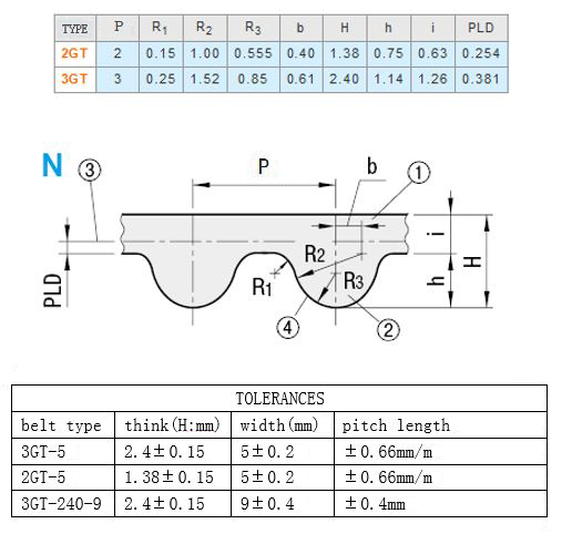
has anyone used the steel strand reinforced white GT2 belts?
I don’t. They are the only people willing to pay usually.
3 Likes
Nice design, only couldn’t figure what’s holding belt not to slip back inside that chamber around that center core. Seems like belt is going around and coming out. Side metal plate is holding centered. Is there any pressure to belt on that side? Kind of hard to see inside. Thanks.
I believe they rely on mating between top and bottom teeth at the exit point, the same way as if you had used tape or heat shrink to mate some top to bottom teeth close to the bend.
The advantage of this design is that this piece is reusable and adjustable.
1 Like
The gap between two jaws on output is too far. But I believe Phil know what he is doing. I’ll wait for second video.
I assume the gap must be <=2*H-h
So, if this is meant for 3GT, it should be no more than 3.66mm. The stock 2GT from inventables would be 2.01mm thick when sandwiched and this is probably why the gap seems big to you. You could add a shim to make it work for that. Or ask Phil to print one. In a fancy color.
Image below is from openbuilds.
@PhilJohnson maybe one thing to consider would be adding some extra length to the jaws in order to engage more teeth.
UPDATE:
I did some industrial espionage for you. Inventables belt sleeve is 10mm long which means engages 5 teeth in total. In 3GT you should be fine with 4 teeth (12mm). It is also tapered on one end to facilitate entry. You could do the same by adding a slight chamfer on the open side of your jaws. Interestingly, the channel is 2.13mm high (>2*H-h) so the teeth are not squeezed all the way across, I assume again to facilitate sliding the belt in. Side entry makes application easier in your design, you wouldn’t need to add more height to your jaws.
On stock 2GT2 belting, the Inventables belt sleeve has enough tension to hold it together but not enough to keep you from sliding it on and up to the belt clip.
On 2GT3 belting (2mm pitch 3rd gen, which I upgraded to), the belt sleeve still works but the belt is MUCH tighter and the sleeve can’t as easily slide into place, which I personally think is a good.
1 Like
We did not say it’s flawed. Just thinking out loud of a possibility, not knowing about the zip ties. Having those, indeed there’s no need to alter anything. It will be super solid.
Seeing I am not any more needed in the engineering department, I’ll try marketing.
What if you offer a limited version for 10,000$ and hand deliver it, as @Zach_Kaplan did for one Xmas X-Carve. We don’t even have to donate all to charity. (Don’t let “we” go unnoticed).
Accompanied by one free carve with Phil holding one belt. By hand. The customer picks which axis.
5 Likes
I might be using poor words to describe it.
They are compressing the belt together at the teeth just like a zip tie does. When I removed them, you could tell where it was on the belts. On my specific stock belts, with a little bit of force, I could slide it on the belt till it butted up against the clip. We’re talking one or two teeth and all the while the belt is compressed. With the 3rd gen belts being thicker, it turned into using a lot of force to get the belt butted against the clip.
The sleeves are a good design that does it’s intended purposes. They don’t slip or at least haven’t slipped in any of my carvings since I installed them.
But that’s besides the point of this Thread so carry on.
2 Likes
Actually my research shows that GOOP II Max works better than zip ties.
1 Like
I stopped using glue on my belts.
I position them correctly and make sure the clip isn’t bent.
Then I use heat shrink. The heat shrink has to barely fit. It takes effort to put mine on.
This works fine and I haven’t had any slipping.
I plan on making my own clips in the future. I think these are not done right in regards to the belts slipping.
For anyone who’s considering upgrading to 9mm belts and is agonizing over what to do about clips (as I was), I wanted to share my experience with simply modifying the stock steel clips rather than fabricating something new from scratch. A 1/16" carbide ‘corncob’ cutting bit (as widely sold for routing PCB slots/edges) made short work of widening the slots in the clip, using some small jeweler files for cleanup, 9mm 3GT2 belt fits perfectly, and I’m fairly satisfied with the amount of material left on either side.

2 Likes
Just for fun, I 3D printed some belt clips today of my own design (no zip ties, glue, or heat shrink required) and stress tested them with a leftover piece of 3GT2-9mm belt. This is about 50 pounds of dead weight, which incidentally is over 6x the tension you could safely use on an X-carve given the radial shaft load ratings of typical NEMA23 motors.

2 Likes
No, you could think of these ones as being for the opposite (fixed) end. If I were going to use them with a stock-like tensioning approach, I’d add a T-slot for the clips that go on the other end, like what you have in your model above.
I’m going with a very different tensioning approach, however - but that’s still a work in progress. For now I’ve got the modified OEM steel belt clips (pictured above) installed on my machine until I finish the new design.
1 Like
You have a static load on the clip. You might want to try a dynamic load to see if the clip will stand up to movement.
That’s a little less simple to instrument in a basement test though, to be fair ![]()
1 Like
Yes.
I’m looking into doing the 9mm upgrade and am seeing a potential problem with my setup. I have aluminum angle on the inside of my Y rails as stiffeners and I’m wondering if the pulley nuts will rub.
Would someone who has upgraded take a pic of the set up for me? I may need to re-engineer a bit. Here’s my setup for reference.


Any help would be appreciated.